Phone: 07770 397668 for radio repairs.
Text: 07770 397668
E-mail:
service@cb-and-amateur-radio-repairs.co.uk
or np262@yahoo.com
Address: Mr Nick Parker,
8 Pouces Cottages,
Spitfire way,
Manston,
Kent,
CT12 5BU.
We welcome customers in Europe, USA, and Australia; if you wish to contact us please phone: +44 7770 397668
I am recommending Moonraker to all my valued customers that have been phoning me to purchase radio products.
Click on the images to go to Moonrakers website.
This month's news
Original Ameritron Al 811 Power Amplifiers
With the increase of the maximum power limit of the Advance Amateur Radio Licence, I have been receiving several of the Ameritron power amplifiers.
Ofcom Amateur Radio Licence, Notice of Variation
Ofcom have produced the document that lists the changes to the Amateur Radio Licences; it can be download here: - https://www.ofcom.org.uk/__data/assets/pdf_file/0029/278345/amateur-radio-general-notice-decision.pd...Radio and Specialist Audio Equipment Repairs Since 1985
If you are looking for new or used Radio Accessories, Antennas, Plugs, Coax Cabling I am recommending Moonrakers online shop.
I would like to bring to the attention to the visitors of my page that I am unable to undertake any work repairing Televisions, DAB Radios, or In Car Entertainment (ICE) equipment, and would recommend googling to find a specialist in that field.
I would like to bring to the attention of our valued customers that due to an unusually high volume of work and the nature of that work I am receiving at this time I still have the intention of achieving a turn-around of radio repairs within 16 weeks, but Radios which have had failed repairs by other people, specialist upgrades requiring the designing, manufacture, and construction of custom components for example UK 40 boards, Roger Bleep Boards, etc. does take a lot longer to install and test; and in the event that we have to source hard to find components for the older radio equipment or communications equipment that has a habit of self-destructing when it fails can also lead to significant delays in the repair time of radio or as is becoming more common a complete rebuild if the radio rather than just a repair.If you would like an update on the repair of piece of equipment you have sent to me then please e-mail me at the normal address shown above.
A Full Amateur Radio Licence holder who passed with Merit.
Call Sign: M0NKL
Images and descriptions of Radio equipment I have repaired over the years
Along with information on components to avoid
Cobra repair and restoration
This radio shown above came to us with a damaged case and front bezel, no TX power output, and an intermittent problem of the meter pegging out at full scale deflection while on receive.
As you can see from the above picture we were able to repair the faults and restore this radio to its former glory.
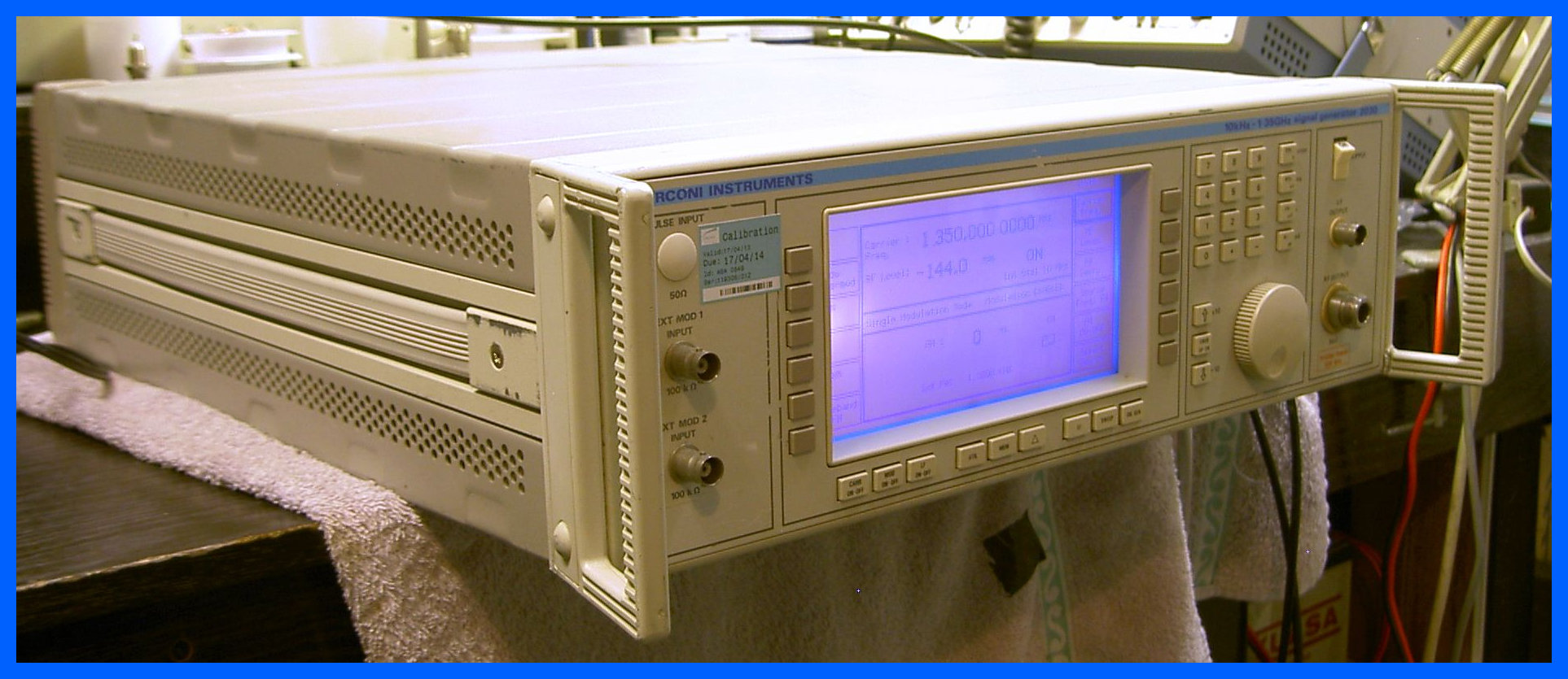
Marconi Signal Generator
In 2017, I had just purchased a replacement Marconi Signal generator, as you can see I am just giving it a test on the workbench before moving it to its new home ready to be used.It is bigger than I expected, but it will provide additional features including a wider range of frequencies, FM and AM modulation options and CTCSS tones that we didn't have access to with our previous signal generator.
A sad sight: Rusty Components
When I take the top off a radio and see rusty components, and a badly corroded board; it is really to late for me to repair the radio.
Magnum Delta Force
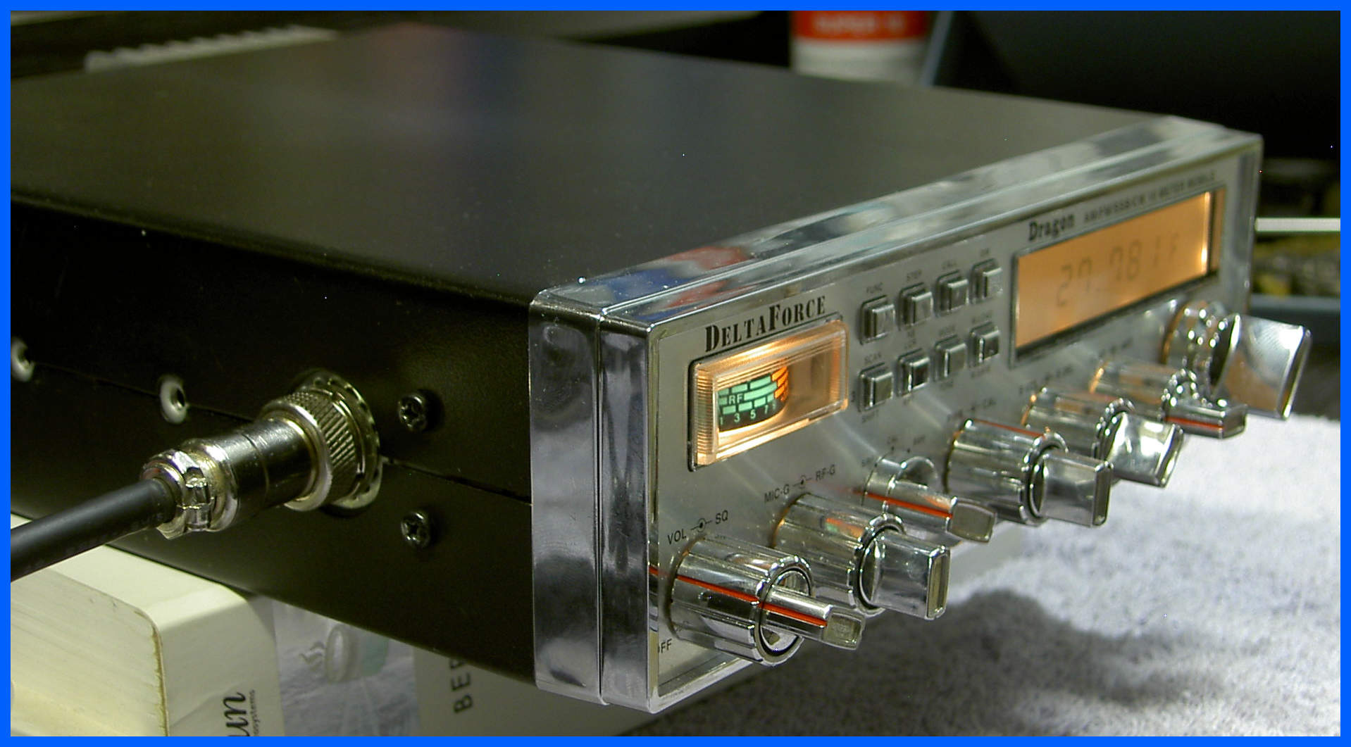
We have an interesting collection of Radio’s this month in for repair, so I have highlighted the Dragon (Magnum) Delta Force, it came in with the normal Single Sideband(SSB) signal meter showing full scale deflection with no signal present, and weak transmit audio on SSB.
Super Star 7000 DX
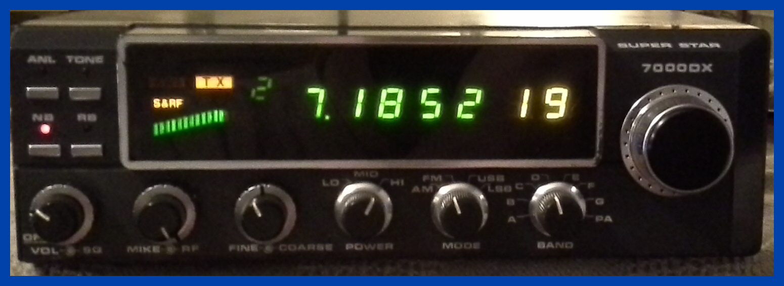
This radio came in with a melted power socket, each mode was on a different frequency, and only transmitted 20 watts maximum on any mode.
This radio was given a recap, service and realignment so that all the modes operate on the same channel frequency, and the power was restored to 50 watts on FM/AM and 120 watts Peak Envelope Power (PEP) on single sidebands.
The above pictures shows the working Super Star 7000DX being tested on FM transmit into a dummy load.
Ham International Jumbo
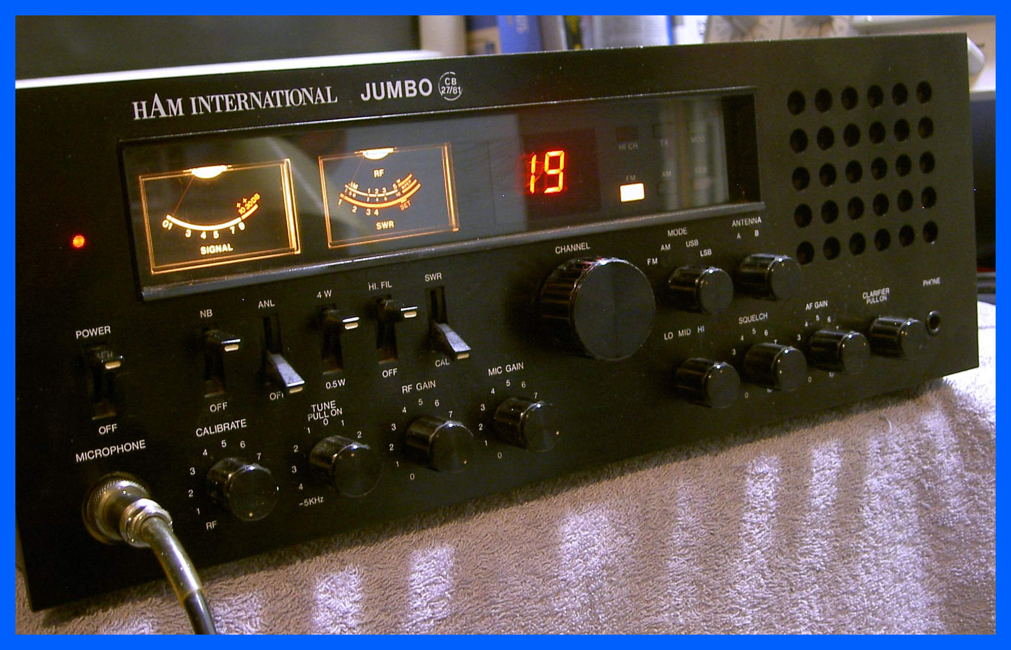
Another Radio that we have not seen for a while is the Ham International Jumbo, it arrived with a report of no receive audio on SSB/AM and wouldn’t transmit on any band.
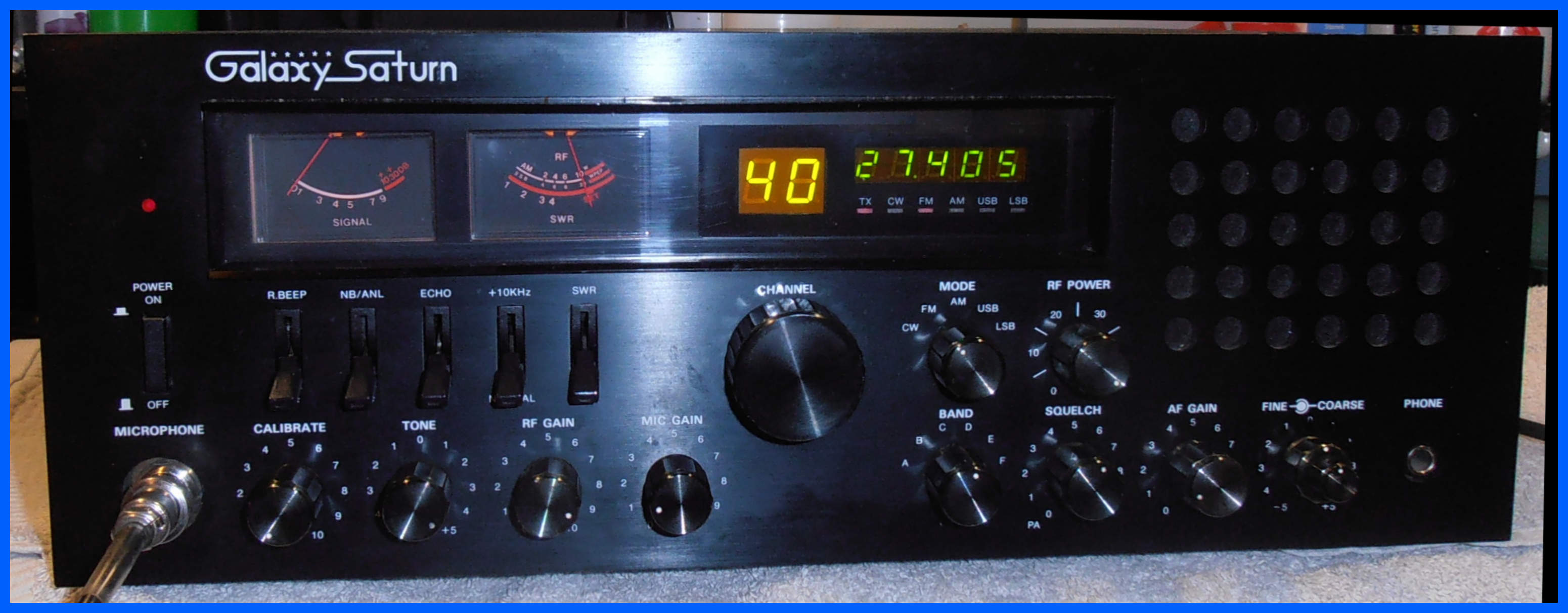
Galaxy Saturn
A visitor to our Facebook page commented on the Ham International Jumbo, well I have posted a picture of one of the later replacement radios which I have just finished. Notice I shown this radio transmitting on FM. I really like the addition of the Frequency counter so you now have an idea on what frequency it is transmitting.
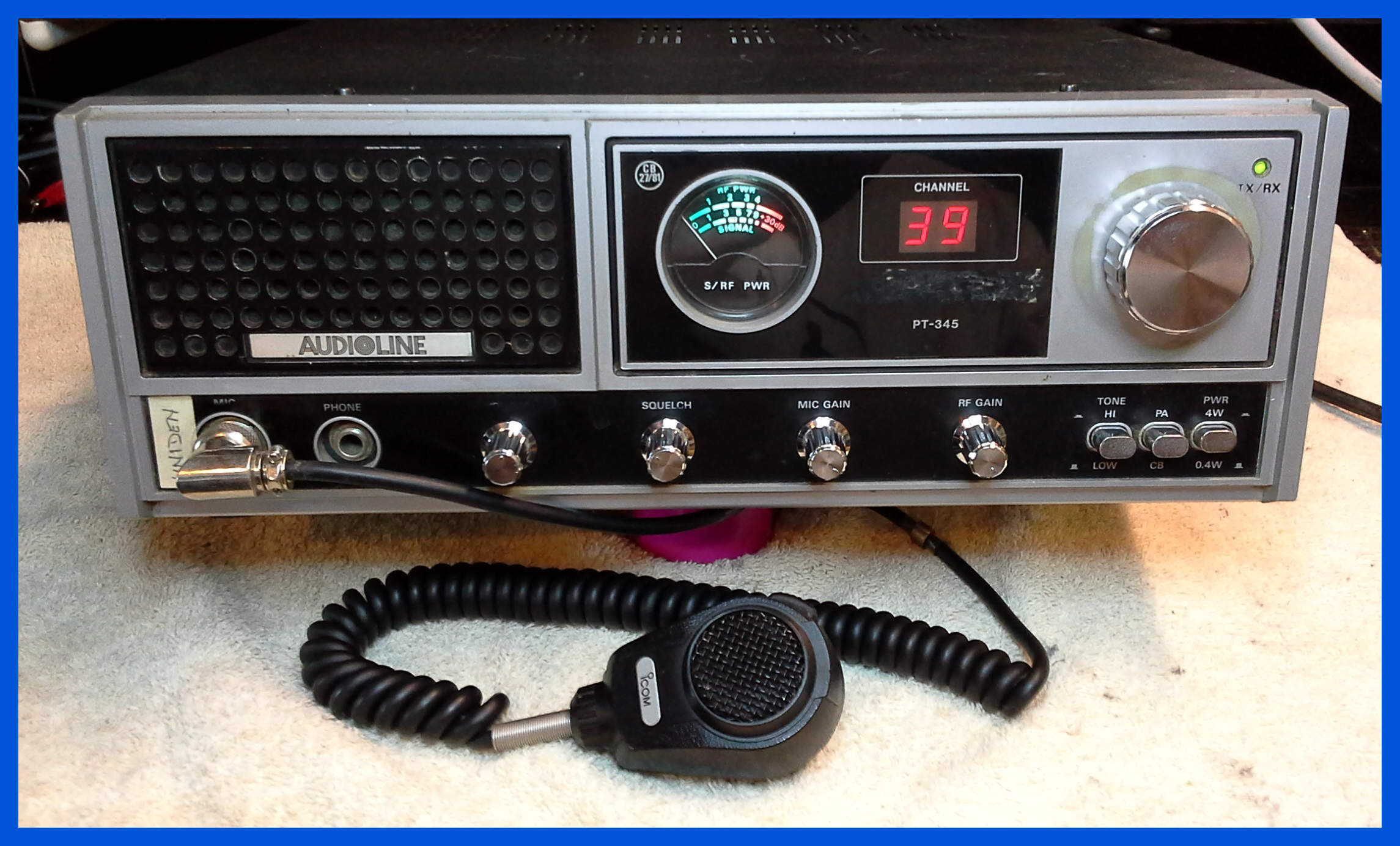
Audioline PT345
This CB base station radio came in with many faults which included the channel display had segments missing, the channel control only tuned to 3 channels, and it only transmitted 2 watts even though the front meter read 4 watts, the meter lamp had blown, and the power supply had been turned up to 15.6v which had caused a load of components in the radio to give and stop working.
After a lot of TLC the radio was restored to its fully
working state and should see many years of reliable use into the future.
These Audioline radios look very similar to the President CB radios, the main difference is that the president radios have two meters on the front not just the one.
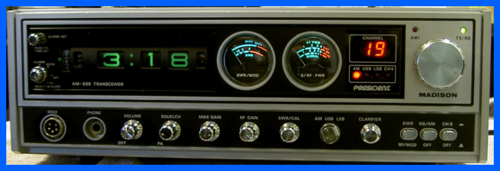
President Madison
I didn’t want everybody to think that I can only repair Cybernet based radio’s, so here is a Uniden based radio I have been working on in the last few weeks.
President Grant Black (PC999)
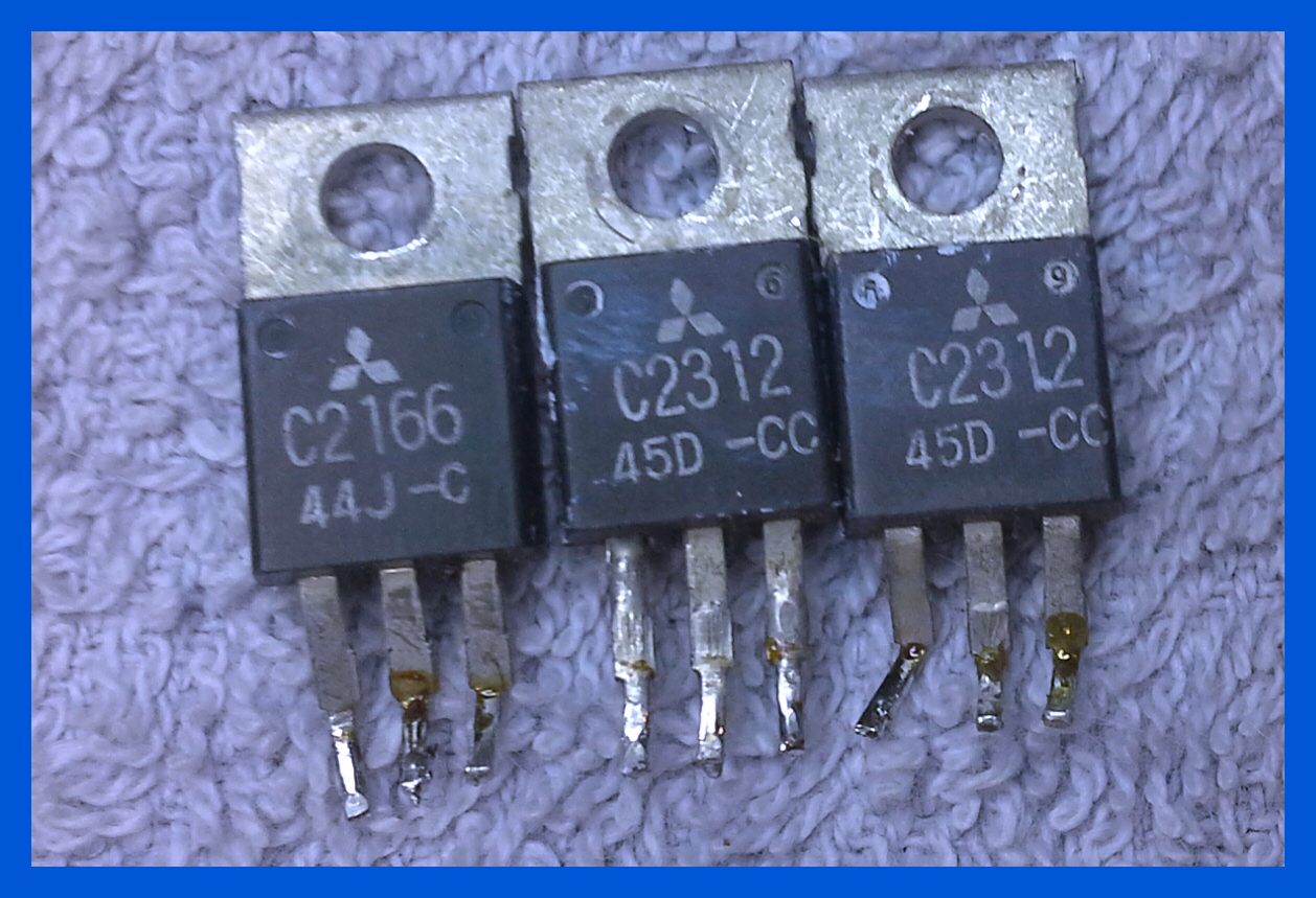
I don't see many of these black bezel radios, and this one came in to the workshop with an array of problems which included having fake PA and Driver transistors, microphone gain control went around and around, it was off-frequency which varied depending on which mode you were using and it needed recapping. After some TLC with genuine transistors and a realignment this radio is back in good working order.
The above image are of the PA and driver transistors which came out of Black Bezel President Grant pictured above. The only differences in their appearance is the labelling which is off-centre and is not straight. The year code is wrong as well. If you needed any more information the middle one only produces a maximum of 1 Watt of power even though they test fine on a multi-meter.
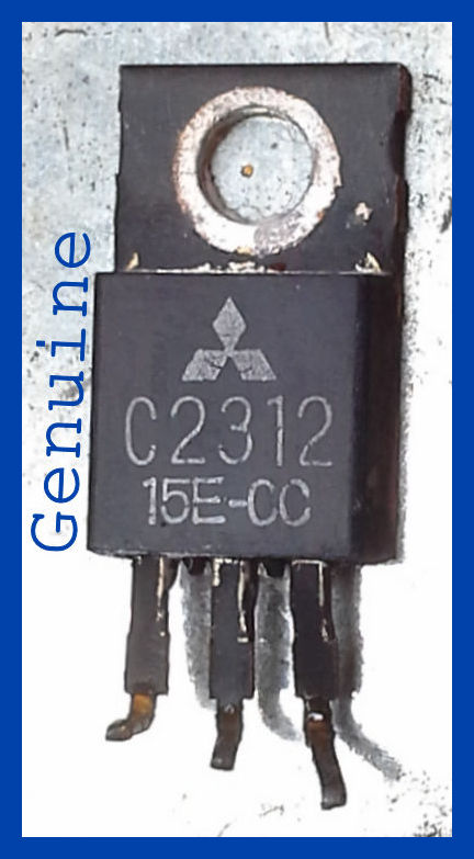
A Genuine Mitsubishi 2SC2312 has straight text, it is a CC version which is high gain and the Date code looks correct.
President Grant (PC999)
This radio came in with digits out on the channel display; after inspection it was clear that the meter lamp was not working, the meter only sort of works when it feels like it and the radio was slow to go into transmit mode. After some TLC the channel display has been replaced, the channel switch was cleaned the meter lamp has also been replaced. A new set of Electrolytic capacitors has fixed all the other problems.
President Grant (PC-409)
This radio came in with some minor problems, but I was surprised to find that this was the earlier version of the President Grant which normally has the PC-999 board in it as shown above; you can tell this is the earlier version of this model because the microphone gain control is only a single control and not a dual control, and because the radio is by default mono-band so the band control is missing although all of the radios that I have seen have been converted to two band versions.
President Veep
This is a small AM mobile set, I have been repairing several of these most of repair is the replacement of the electrolytic capacitors and checking that the Tx power output is correct, they receive and the modulation level is correct. Unlike the teaberry version the AMC control has been removed so you no longer have to adjust it.
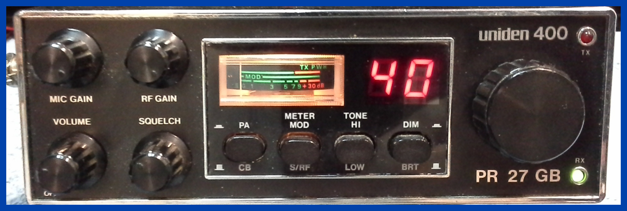
Uniden 400
This radio came in as not working, and after replacing the electrolytic capacitors, and re-soldering some dry joins the radio was tested and worked as expected.
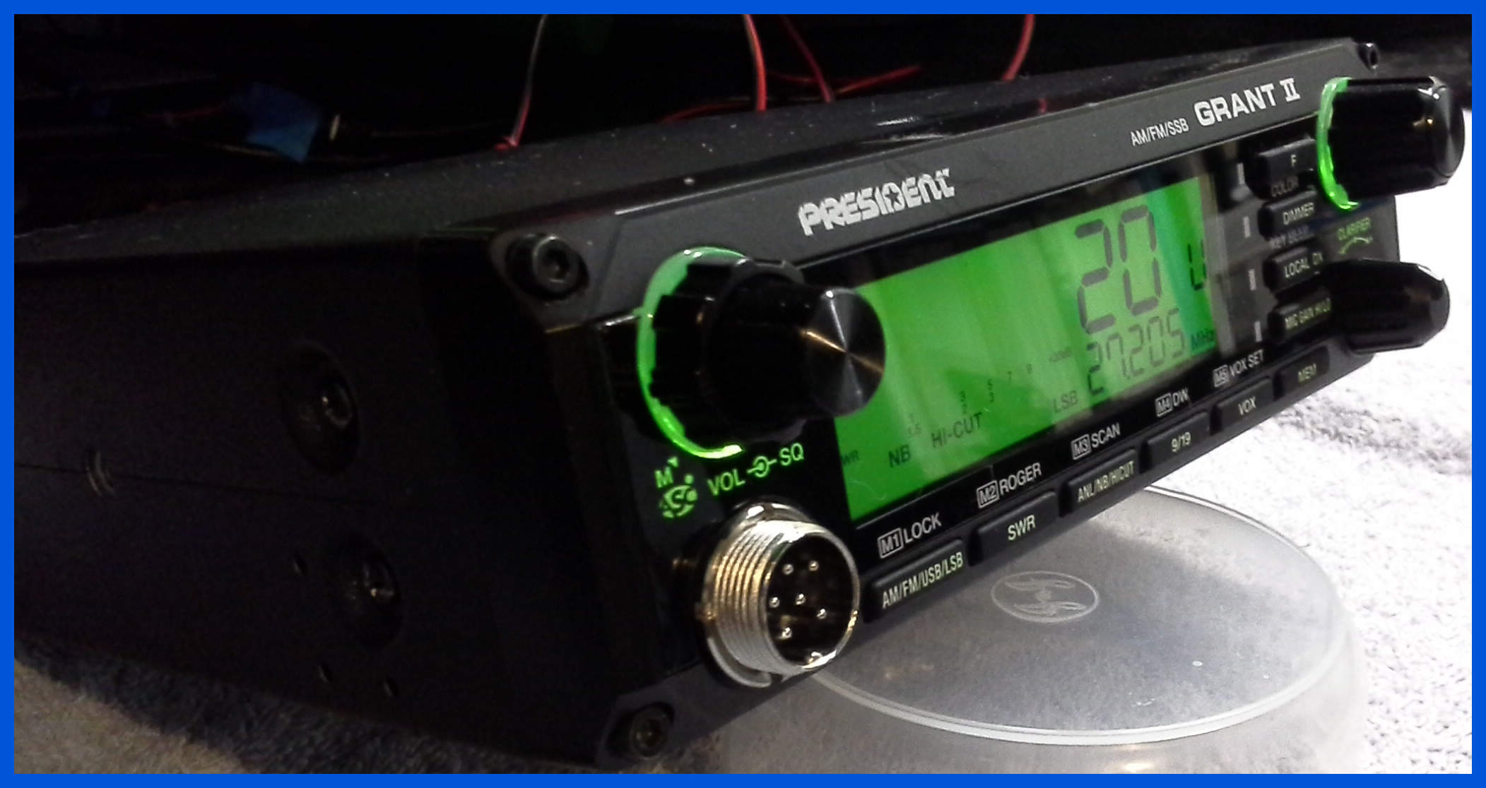
President Grant II
This is the next generation of the Grant which has come a long way from the 1970's version. I don't get many of these radios in for repair because they tend to be reliable unless someone has had a fiddle with them.
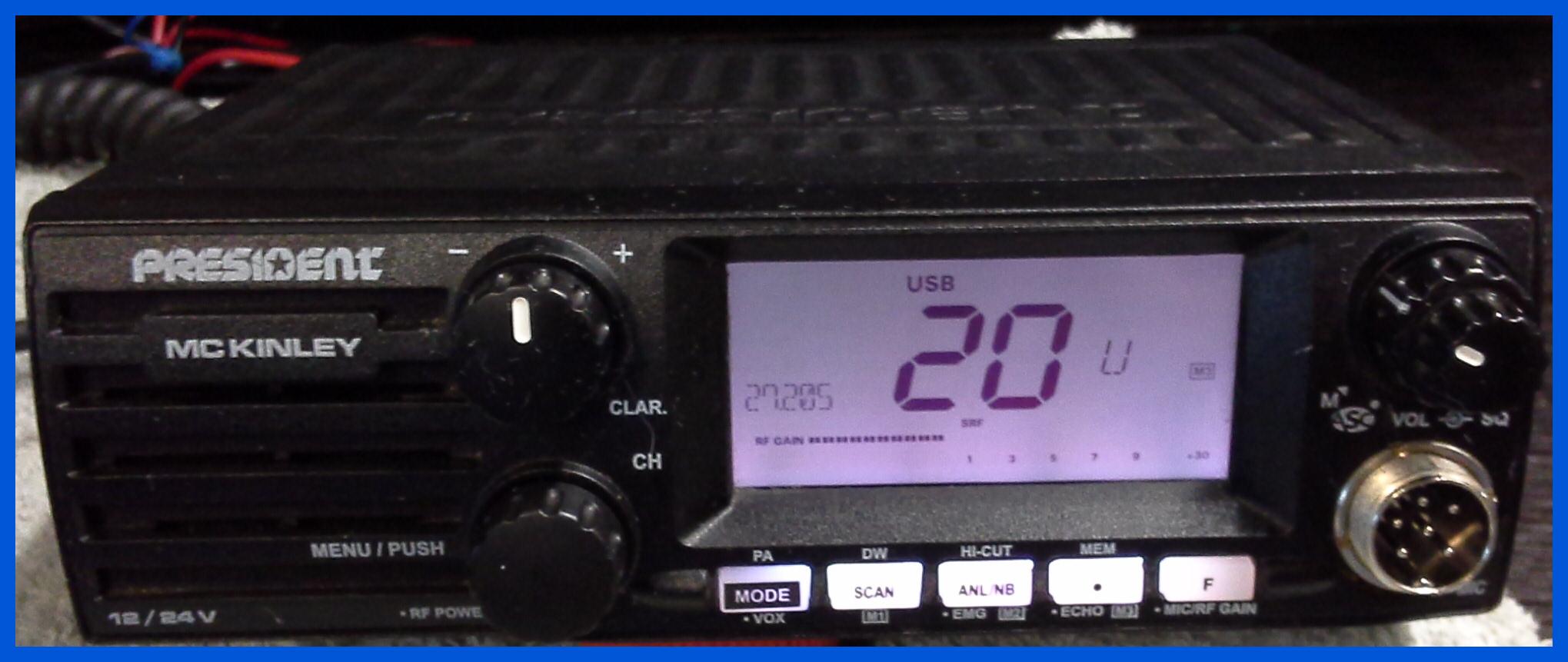
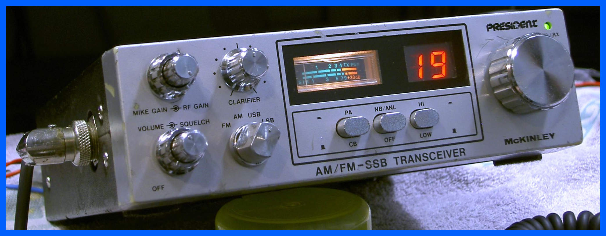
President McKinley
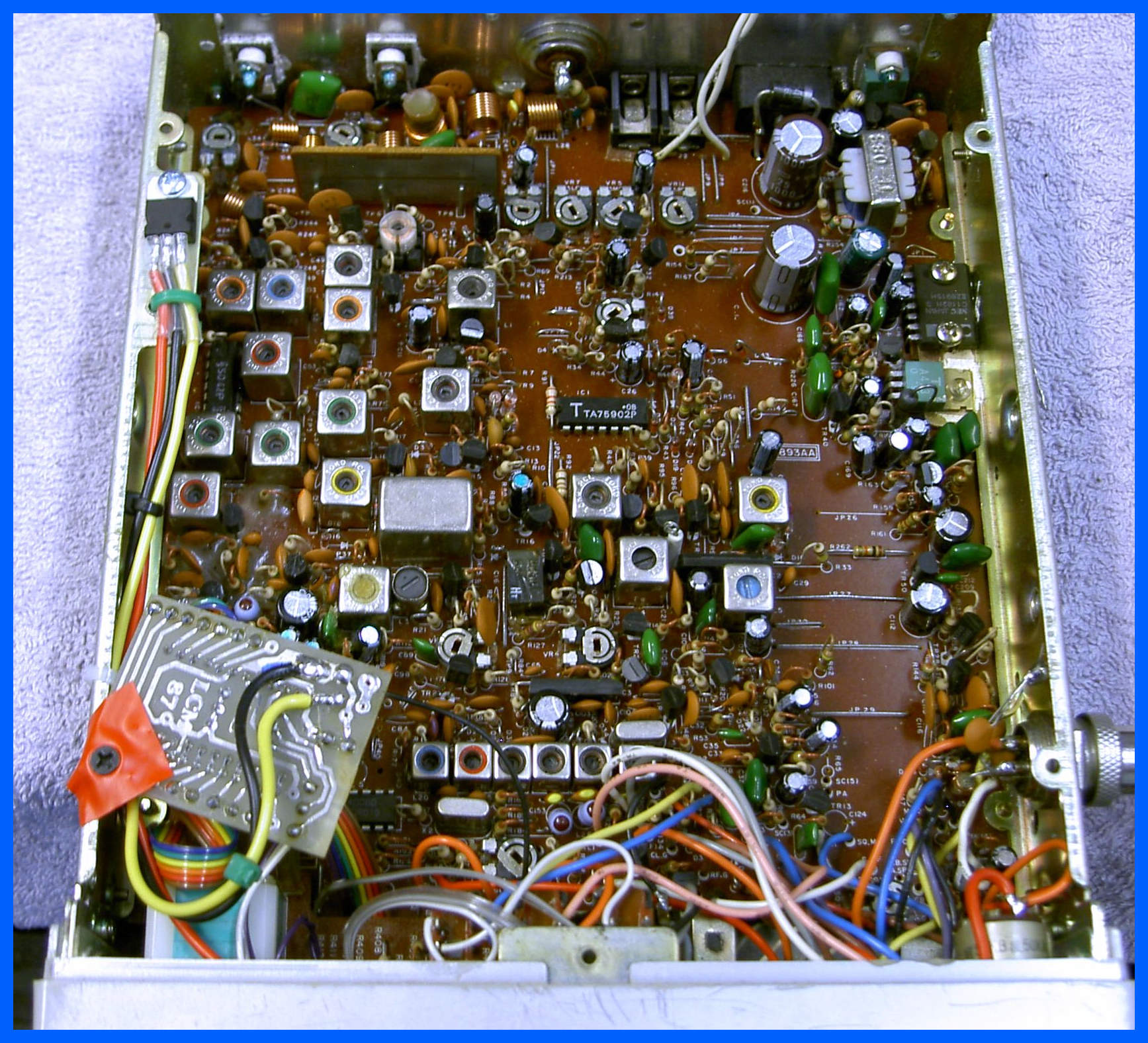
This is another rather good mobile set; this time having the same Uniden board as the Stalker 9 PC893, but not being a Stalker 9 has the alternative UK40 board mounted on the left-hand side of the case.
President McKinley
This is another rather good mobile set; this time being the new EU version with a smaller footprint.
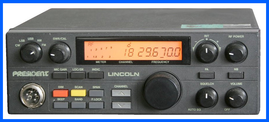
President Lincoln
I have been working hard over the Christmas 2016 holidays,with a lot of my ordered components arriving altogether. This is a finished President Lincoln which has had a new PA Output Transistor and Driver Transistor after it was found that the Output Transistor was Fake and the driver had blown.
President Lincoln (Capacitors)
My latest President Lincoln that came in for repair which looked like a simple problem, but turned out to be very time-consuming when the Electrolytic capacitors had started to leak all over the printed circuit board, and several of them had gone completely short circuit and had blown some components on the other boards.
President Lincoln II
This radio came in with no transmit audio. It looked
like a microphone plug failure had caused the 13.8v supply to go to places it
was never intended and the result was the microphone audio signal tracking had
gone open-circuit and the microphone dual bilateral switch IC had blown as
well.
The microphone dual bilateral switch being a small surface mount IC great care was taken replacing it on the radios main board.
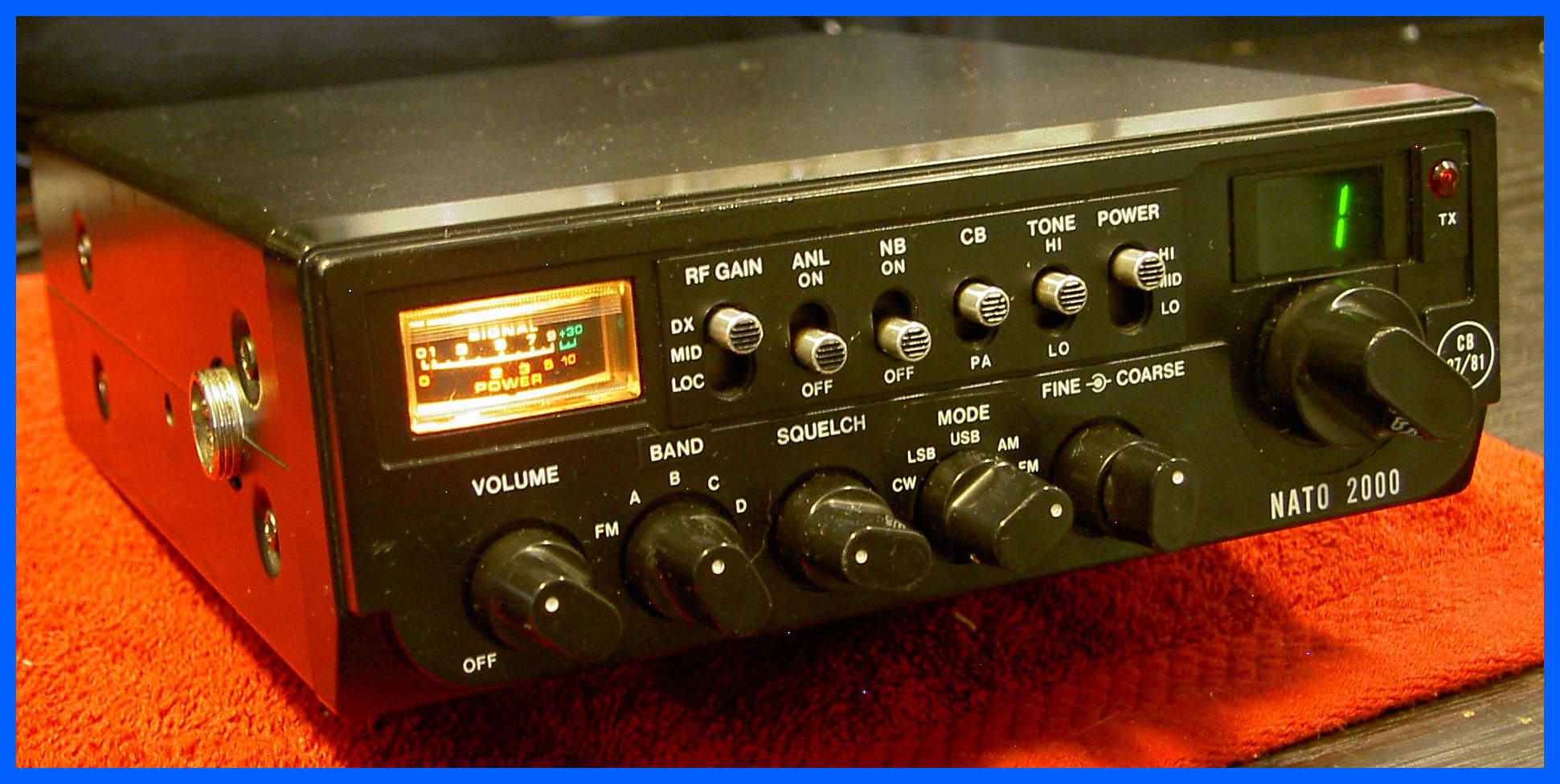
Nato 2000
I have had lots of fun repairing this set, being one of the few sets other than the Stalker 9 with the UK 40 built in as standard.
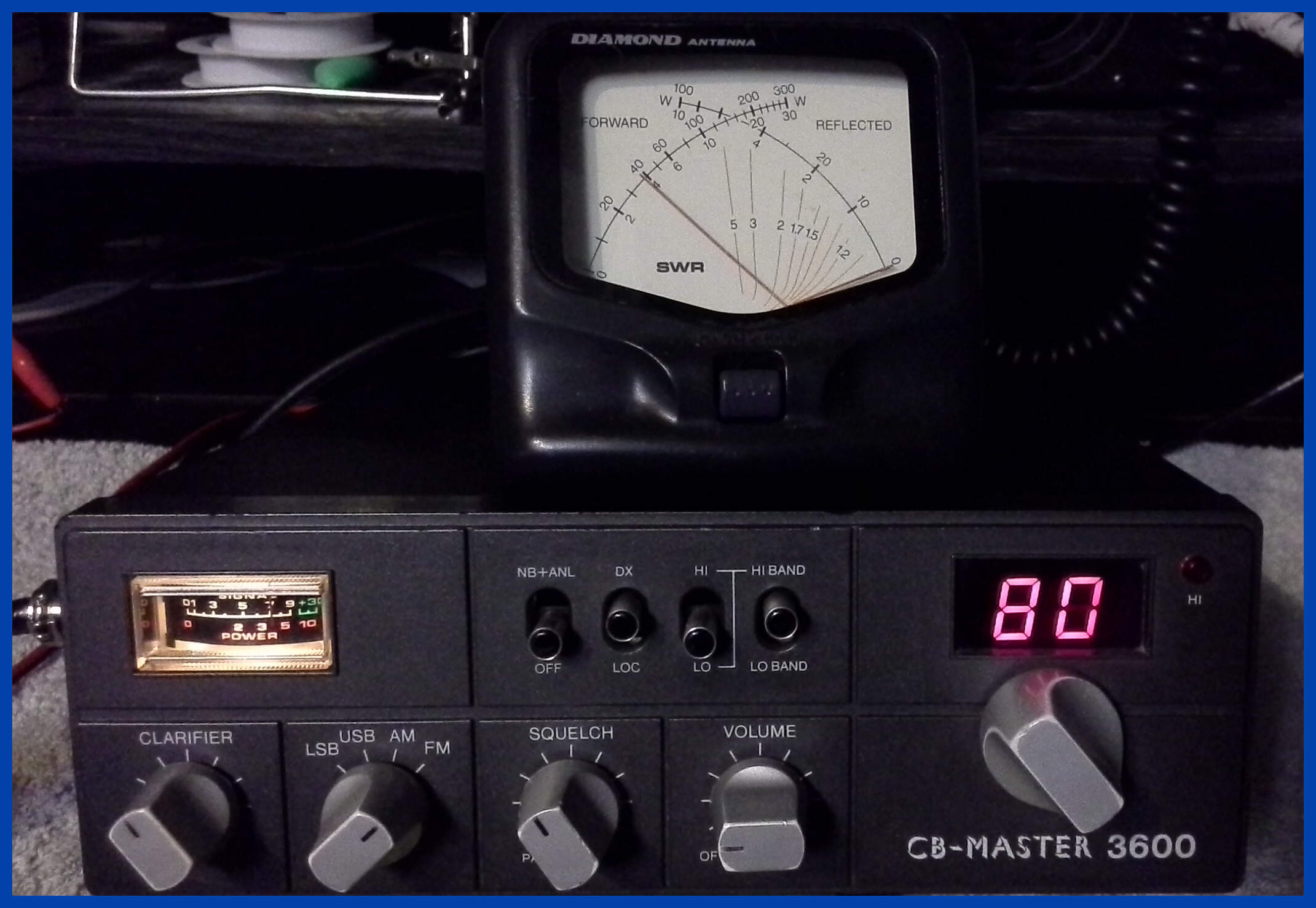
CB Master 3600 Transmitting FM
This Cybernet radio can in with a report of intermittent no transmit, This being a 160 Channel variant of the Ham International jumbo, and Major 588 like the NATO 2000 there are lots of components that fail intermittently.
All the potential problems components were replaced, the Channel change switch was removed and completely cleaned, the heavy components in the transmit path were re-soldered, and all the electrolytic capacitors were replaced.
The PLL was check for correct alignment on all bands and found to be operating with expected parameters compared to my Major 588.
The above picture shows the radio transmitting 4 watts in Frequency Modulation mode.
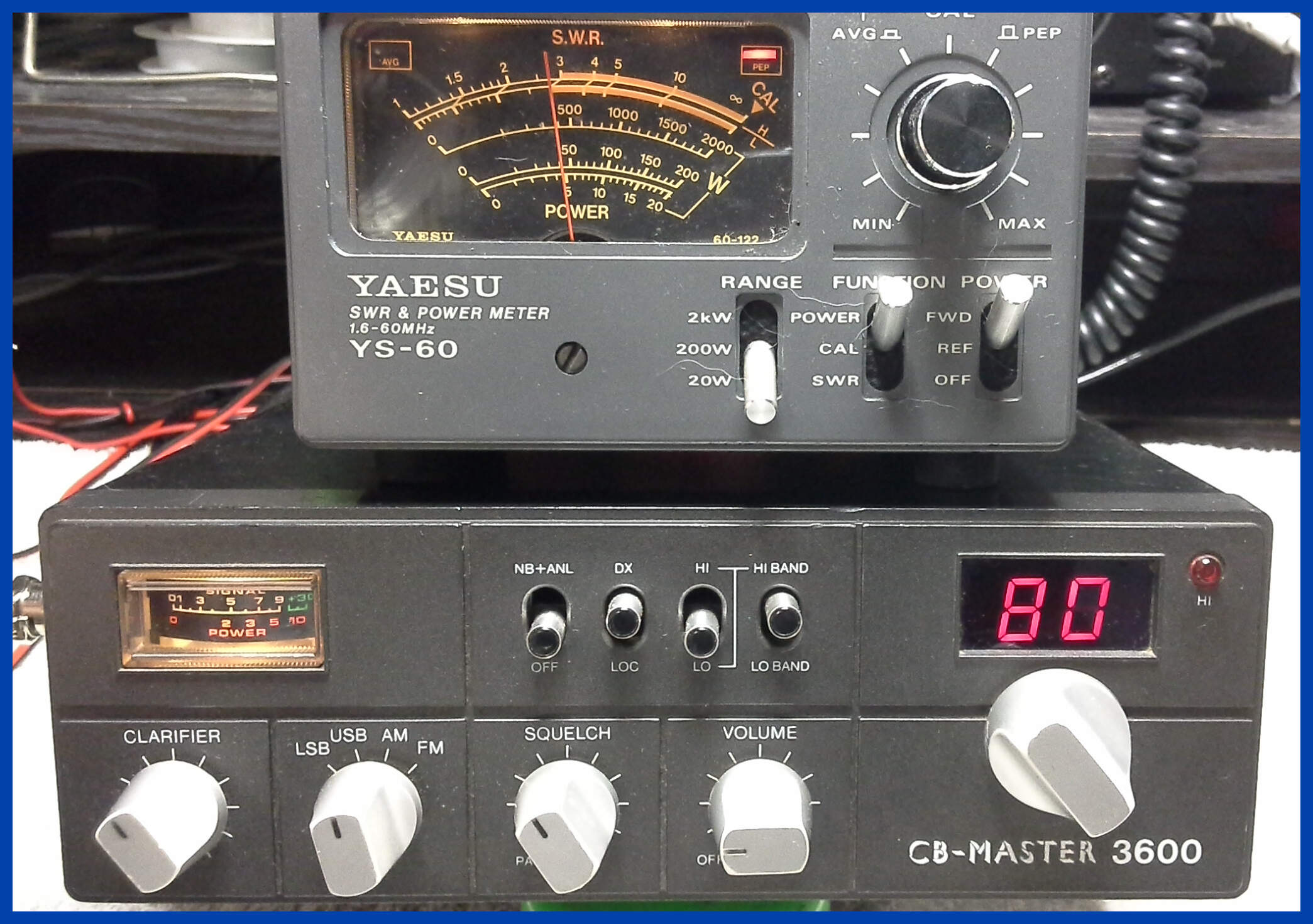
CB Master 3600 Transmitting Upper Sideband.
A follow-on test of Single Sideband Transmission producing 4 watts Peak Envelope Power (Pep).
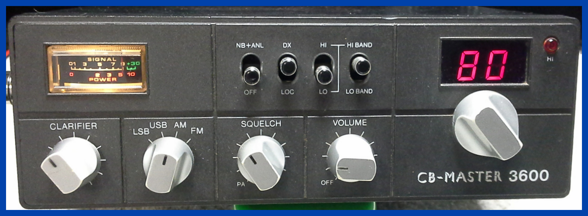
CB Master 3600 on receive
No radio repair would be complete without a receiver test
S9 at 100uV.
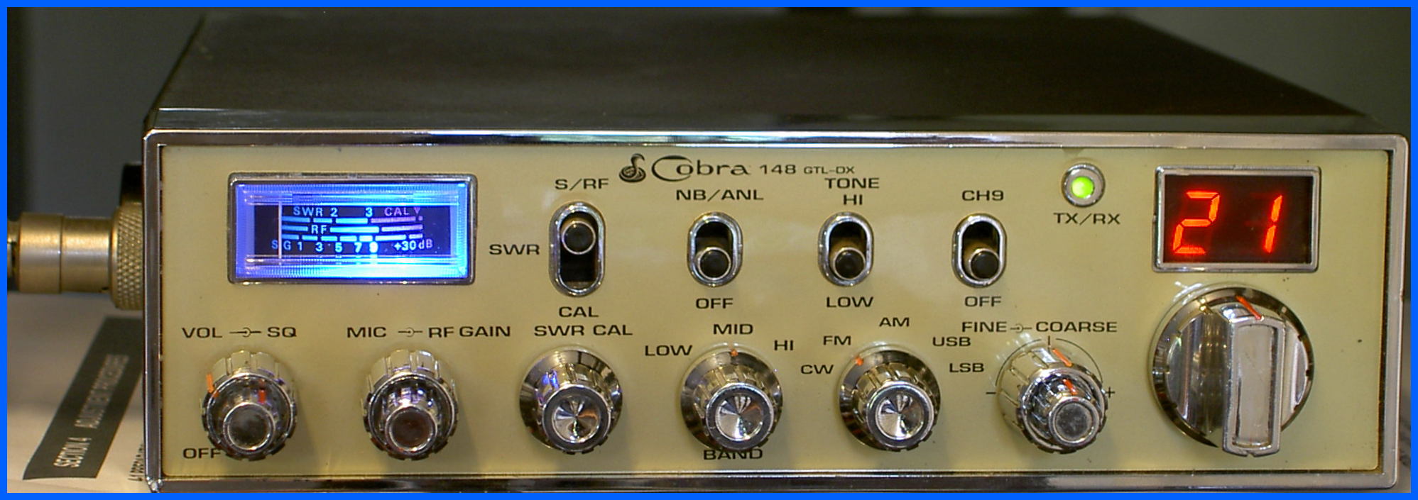
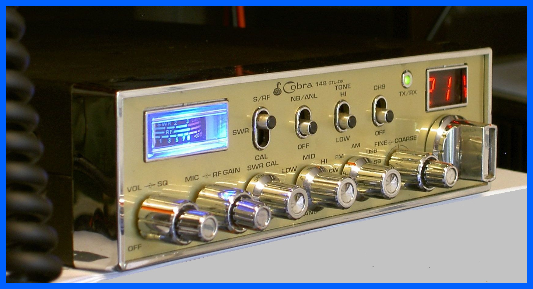
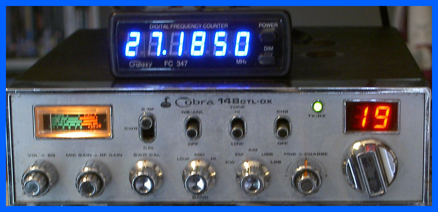
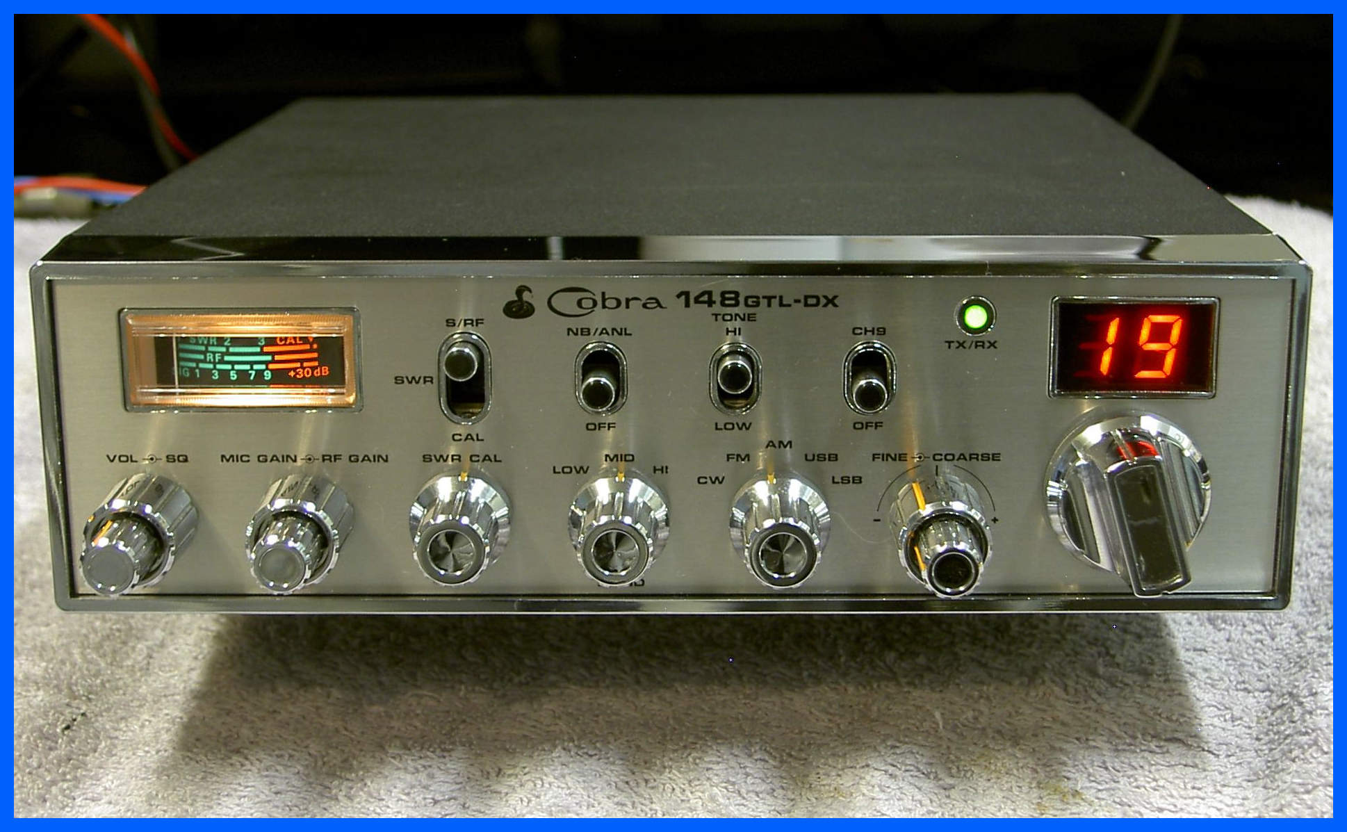
Cobra 148 GTL DX
I have had one of the best examples I have
ever seen of a
Cobra 148 GTL DX, which had not been screwdrivered or seriously modified, so I
had to photograph it and show you all because this is a once in a lifetime
experience.
Cobra 148 GTL DX with a fitted Frequency Counter
I have just serviced this Cobra as well as installing a Galaxy frequency counter. The frequency counter is supplied with the ability to be screwed to a desk or shelf, or if you prefer comes with pads to stick it to the top of the radio. This frequency counter is the latest version supplied in blue and gives you the additional digit over the previous model fitted as standard into the Superstar 3900.
Superstar 3900 UK40
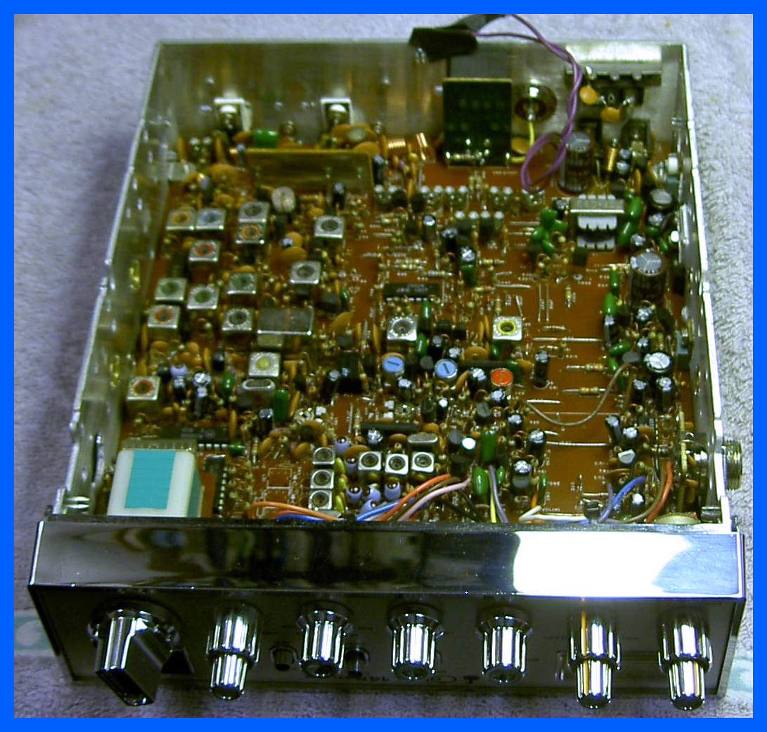
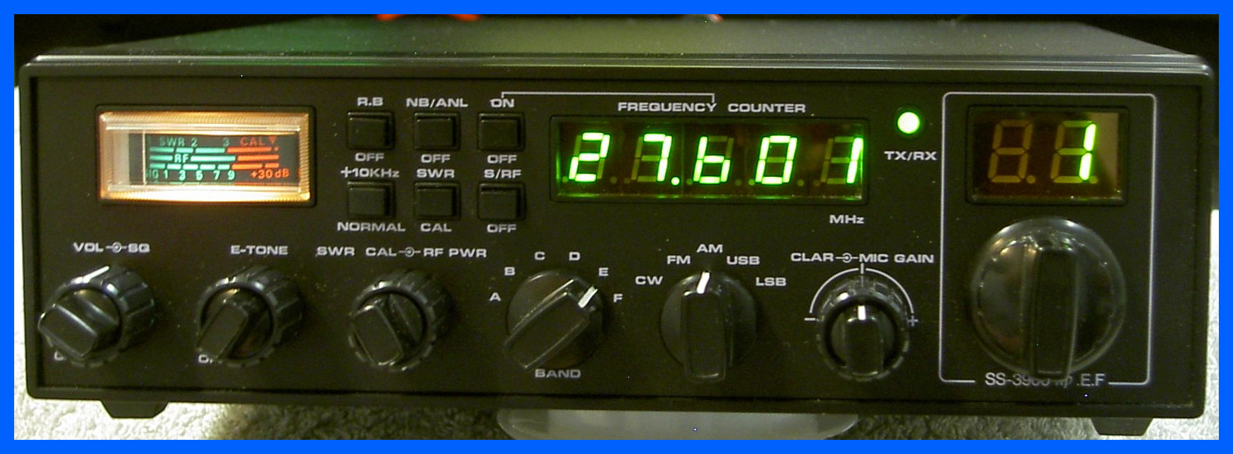
This radio came in to have the new UK40 Board fitted and as you can see worked perfectly; I also did some routine repair work which came to light when the covers were removed and the radio was tested.
Super Star SS158EDX
This radio came in with lots of problems, the main one was someone had tried to realign the radio, and the radio was off frequency on all modes and all bands, it also didn't work on AM.
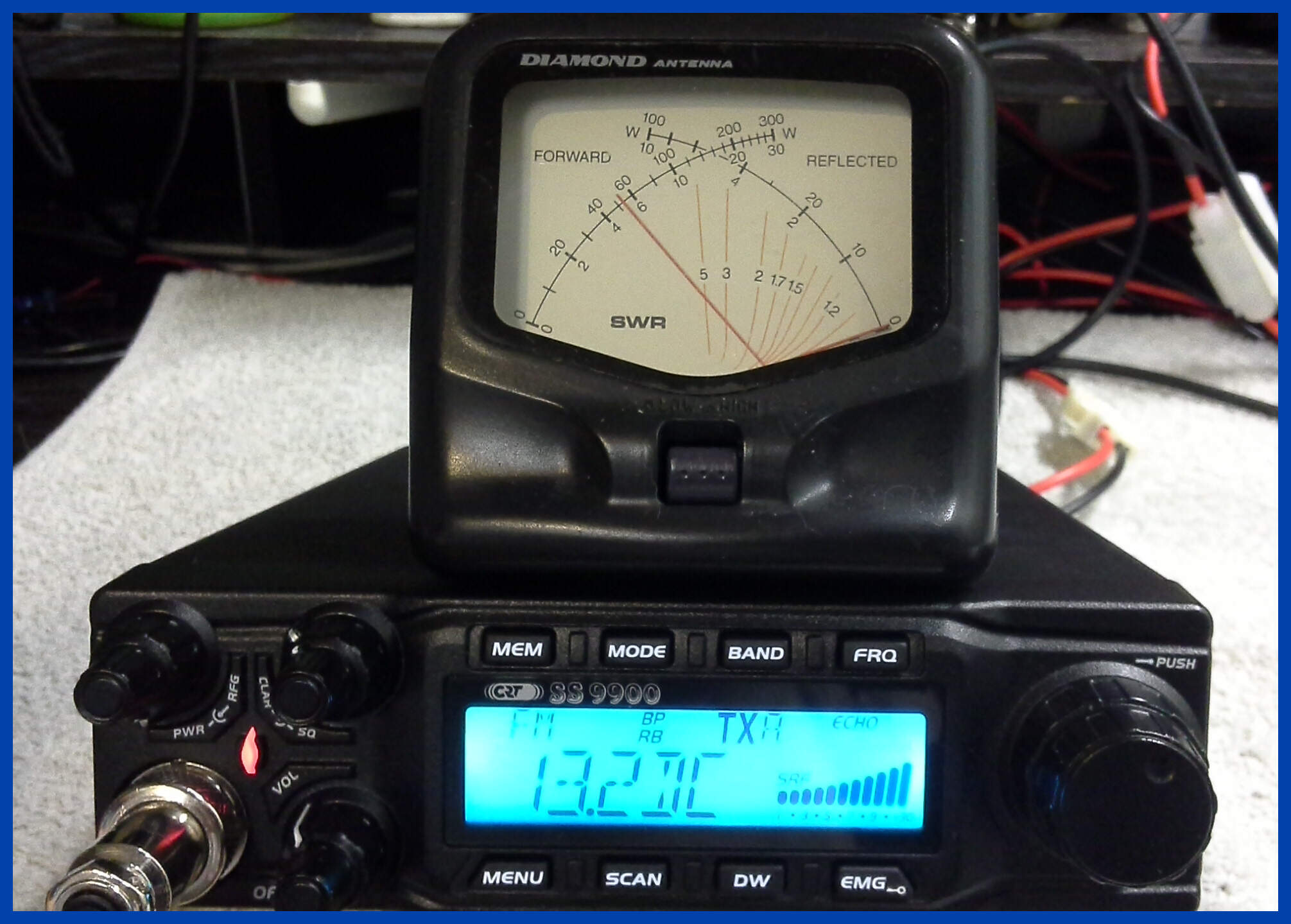
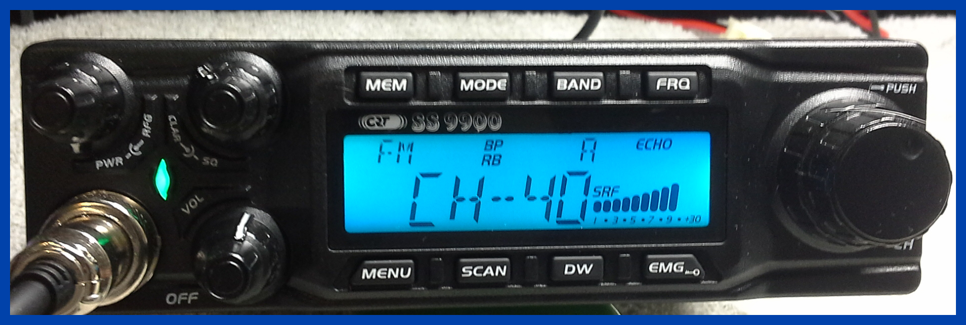
CRT SS9900 Transmitting FM
This radio came in with very low power, which is strange considering both PA Mosfets had blown with gate to source short; I would have expected there to be no RF power output. I fitted some new PA Mosfets, and rebiased them. The picture above shows the radio being tested on transmit, producing just over 50 watts on FM into a dummy load.
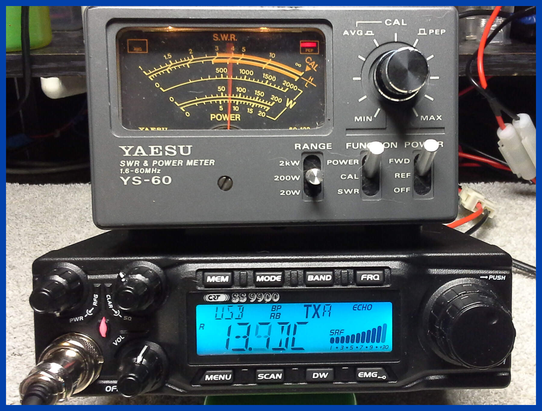
CRT SS9900 Transmitting SSB
A follow-on test of Single Sideband Transmission producing 70 watts Peak Envelope Power (Pep).
CRT SS9900 Receiving FM
No radio repair would be complete without a receiver test
S9 at 100uV.
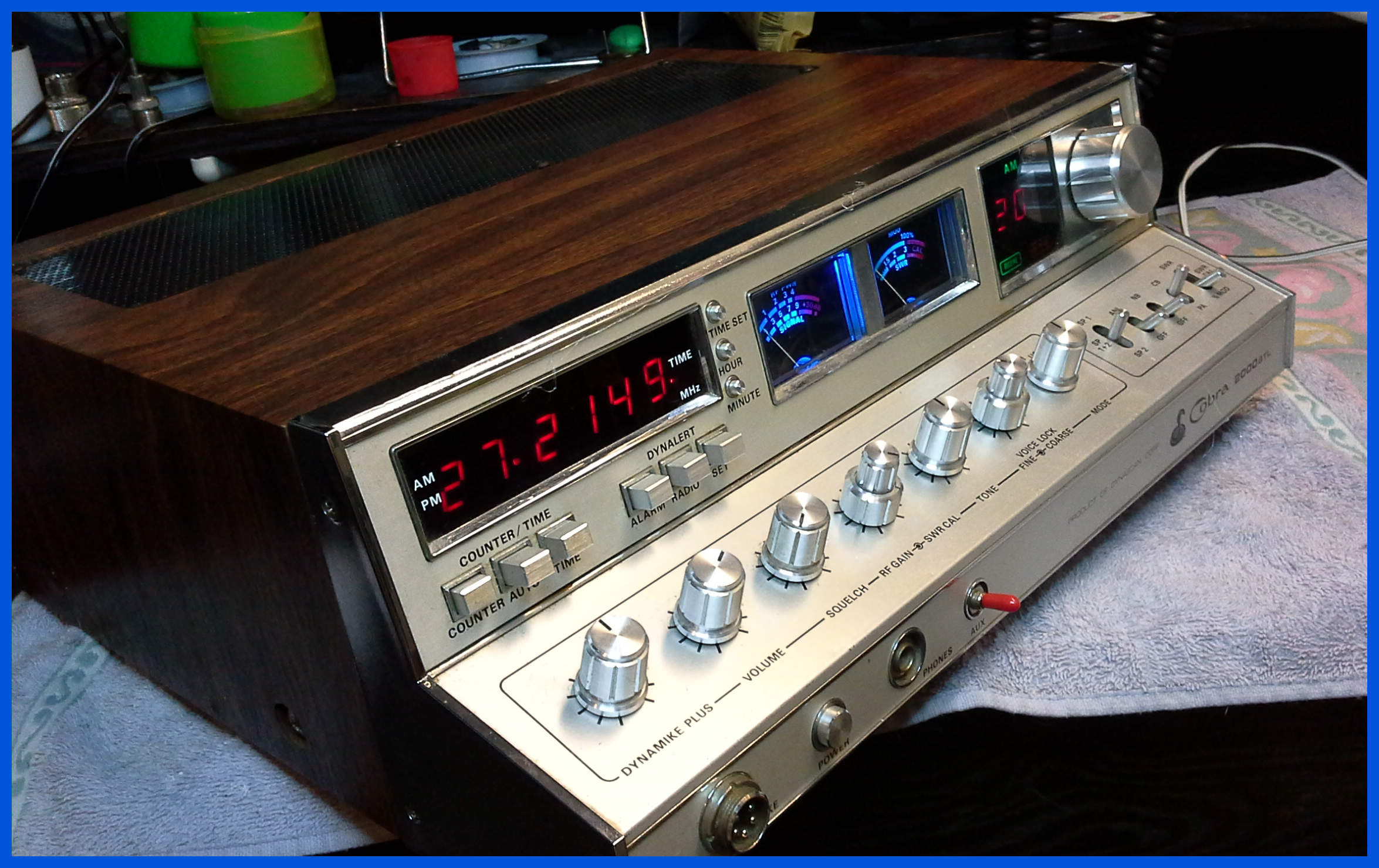
Cobra 2000 GTL
From the days when CB radios looked like a piece of furniture we have a Cobra 2000 GTL with the original Uniden PC board and Uniden capacitors. This radio arrived a little worse for wear but after a lot of TLC it is coming back to life and is looking like it should. There is no internal speaker and I don’t have the original speakers, so I assume they have been lost over time. I really like the real frequency counter something we are seeing again in the superstar 3900 and Magnum range of radios.
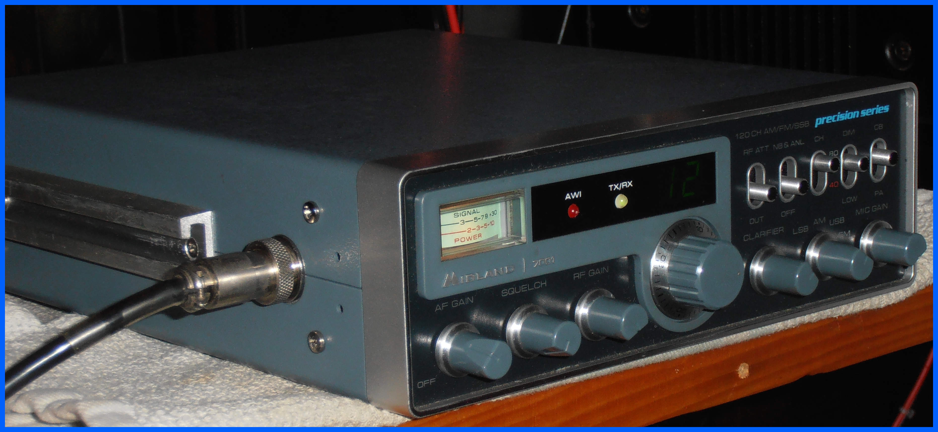
Midland 7001
You are looking at a rare Midland 7001 multi-mode radio in very good condition sitting on the test bench; it came in with no Tx/Rx, and after a lot of work I am pleased to report that it has come back to life.
Galaxy DX 66
This radio has had some interesting modifications performed on it some of which I have had to repair, so I just couldn’t resist posting a picture of the finished radio.
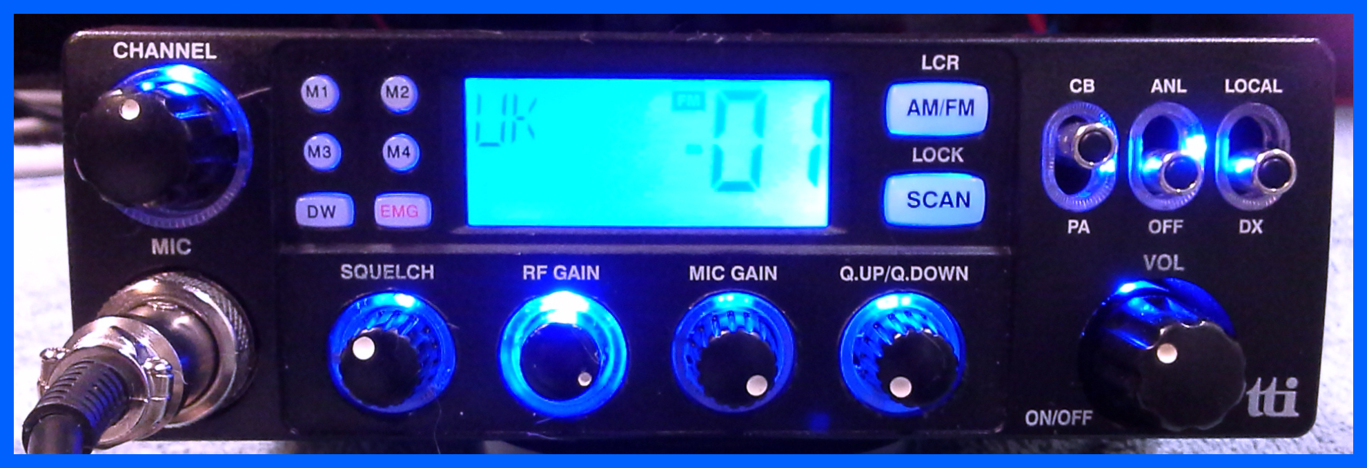
TTI TCB 880
This radio came in with many problems the first being
that the
radio turned on with the LCD performing its self test, but the radio
didn’t transmit or receive anything also the LCD backlights was not
functioning.
The power cable had no inline fuse or insulating grommet where it passed through the metal case.
Communicator NI440DX
This is a UK40 CB radio that came in with a few problems interesting problems and requiring a service. Once it was recapped and realigned and a few of its blown components were replaced it came back to life and works like new.
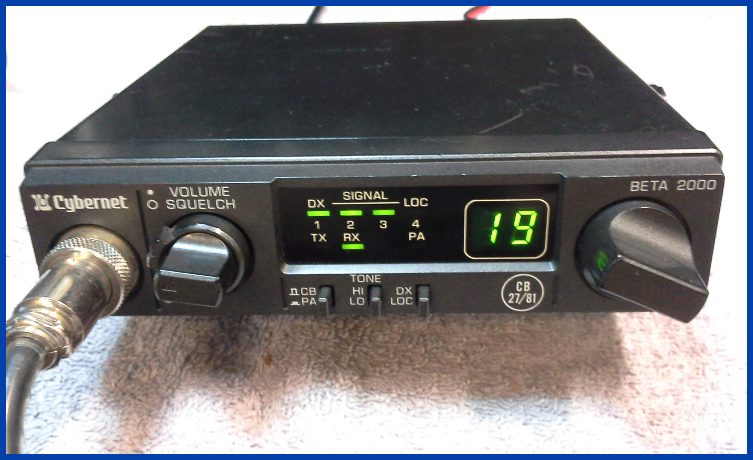
Cybernet Beta 2000
This radio has had a repair of the front bezel and the control switches, and some general maintenance while it was in the workshop. The picture above shows it on test receiving an S9 signal.
Realistic TRC 44A
I thought I would share with you one example of what I have been repairing this month which is a Realistic TRC 44A in excellent condition.
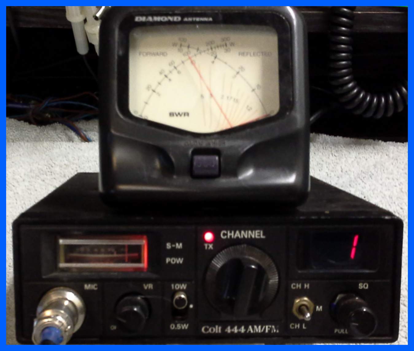
Colt 444 AM/FM
This is a tri-band AM or FM transceiver with variable power settings.
This radio shown above is in receive mode with 100uV of signal, it has had a new meter installed, notice the green Rx lamp on the left of the meter.
A collection of strange modifications have been removed because they didn't do anything useful, the radio has been recapped, and had its frequency aligned.
The fuse hold has been replaced because the one supplied broke into lots of little bits. the front plate has been glued back on.
Colt 444 AM/FM (Transmitting)
This radio puts out 10 Watts on the high power position into a Dummy load which is quite a lot for a radio of its time, it has a three position power switch so you can turn the power down to 4W or 0.5W.
Teaberry Stalker IV
The Stalker IV is a 40 channel AM only mobile transceiver.
This radio required a recapping, and had a lot of dry joins re-soldered, as well as a new to the radio front bezel was installed.
The radio in the picture above is shown receiving a 90% modulated carrier at 100uV before being put on the test bench for a reliability test.
This radio is a classic example of a radio that stopped working after being on the test bench for three days; it turned out that the PLL chip and PLL mixer chip had failed due to the shock of suddenly being used after a very long time in storage.
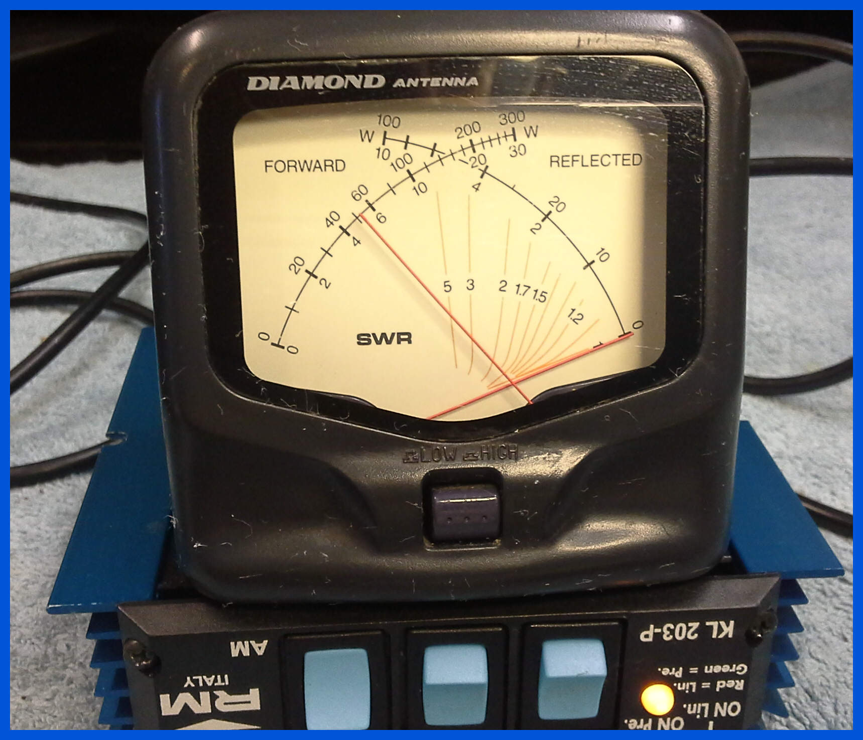
RM Italy KL203P
This power amp came in with the Rx Pre-Amp not working. A relatively simple problem to fix, the biggest difficulty is getting the covers off and back on again being a friction fit without scratching them.
Pre-Amp Off; signal generator signal. (-40dBm)
Pre-Amp On ( -26dBm a gain of +14db)
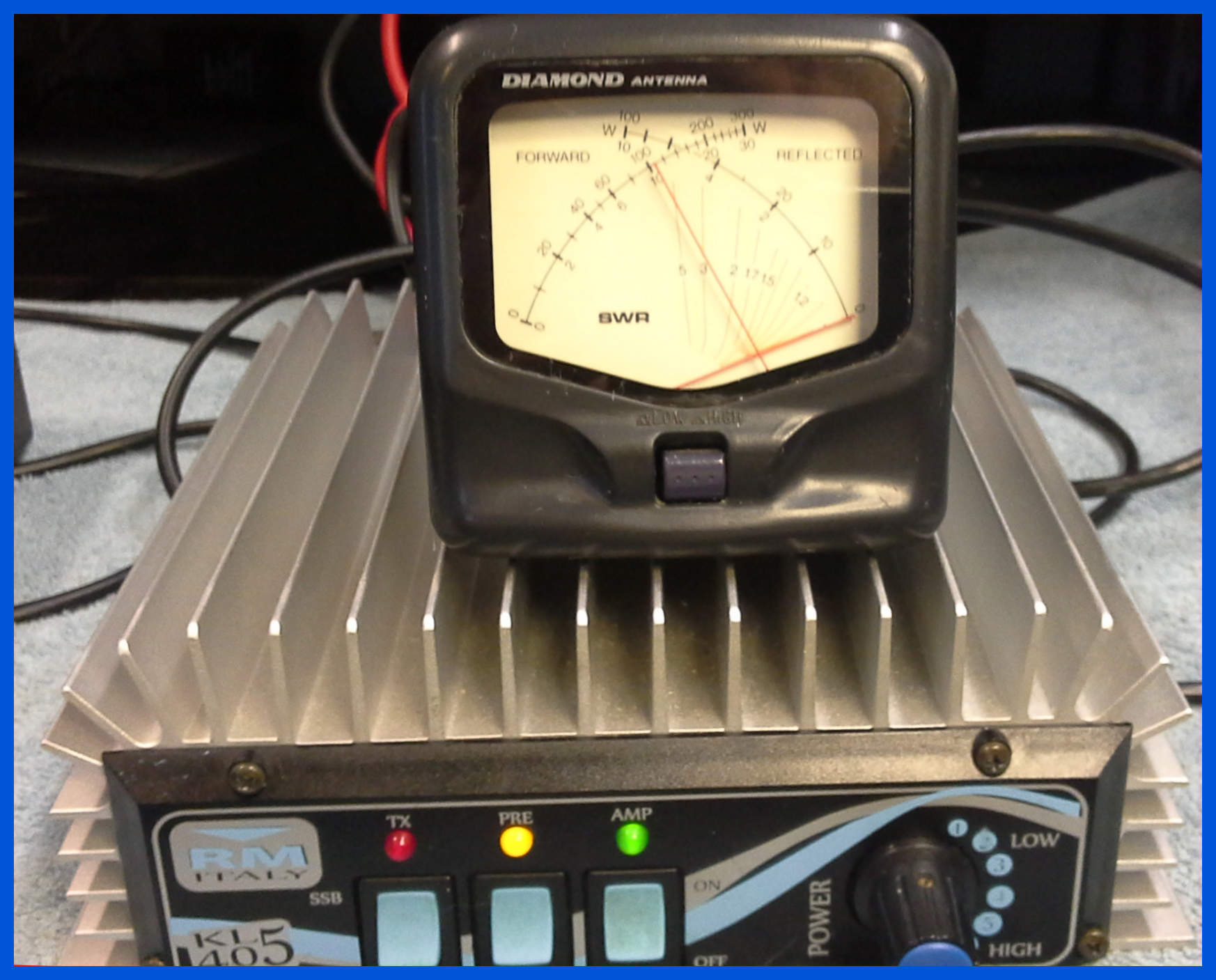
RM Italy KL405
This power amp came into the workshop with the Rx Pre-Amp not working. A
relatively simple problem to fix; the difficulty is getting the covers
off and back on again without chewing the screws.
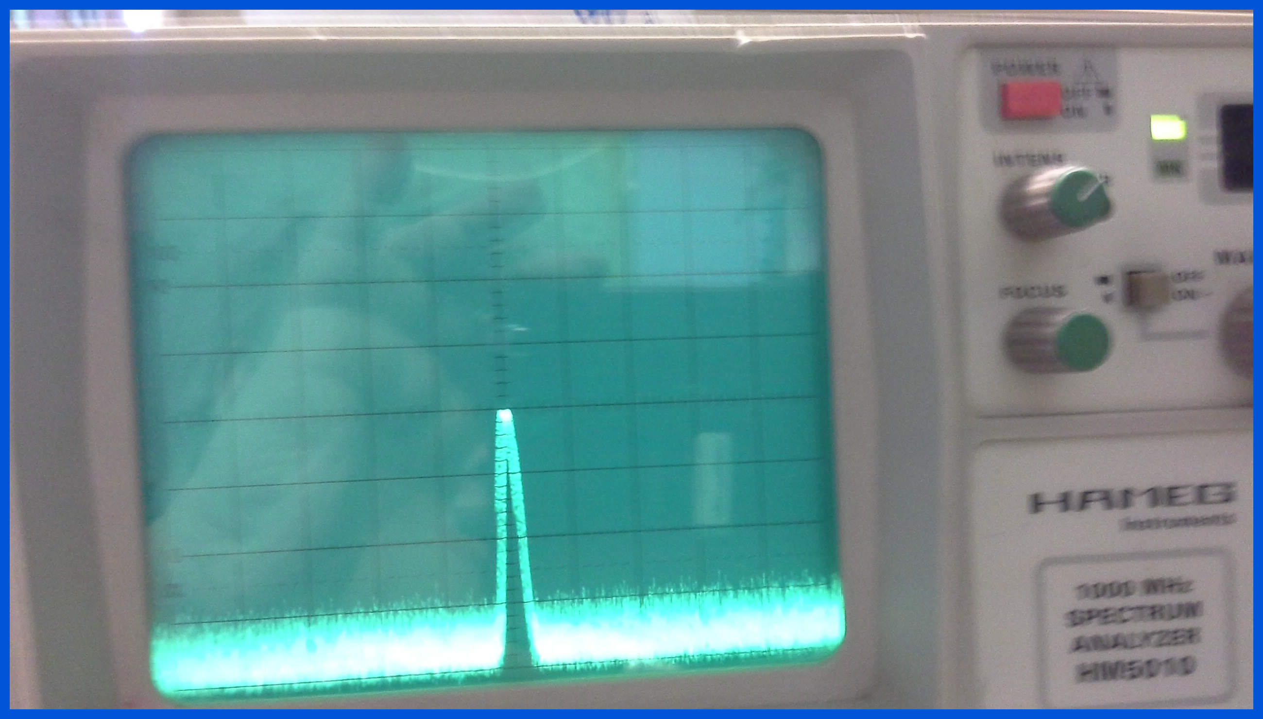
The picture above shows the power amp transmitting with 4 Watts drive from a CB set into a 50 Ohm Dummy Load.
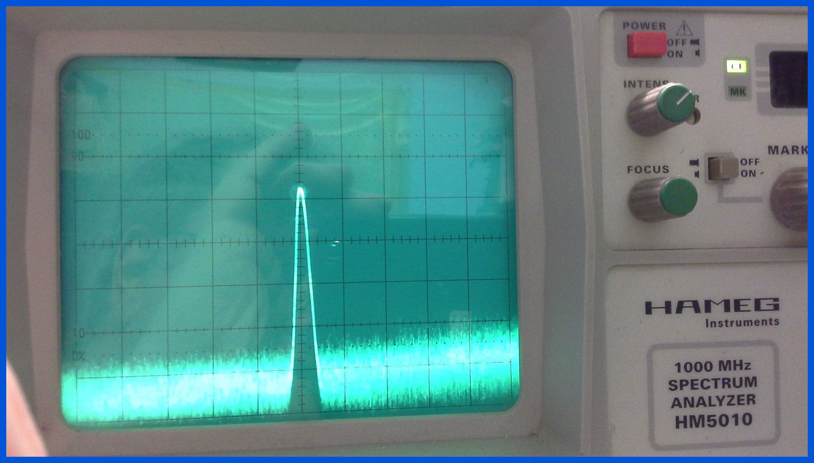
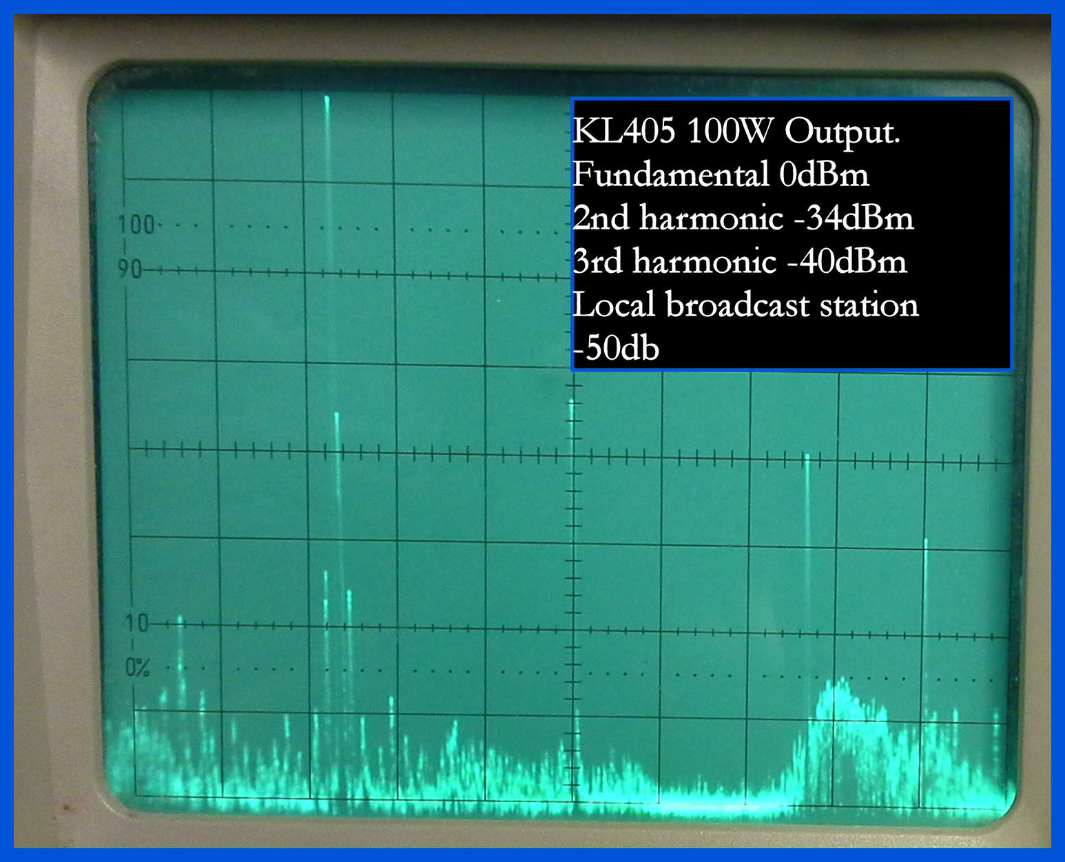
This picture above shows the output power of the amplifier displayed on a spectrum analyser while being driven with 4 Watts drive from a CB set with no modulation.
The legend is shown left to right.
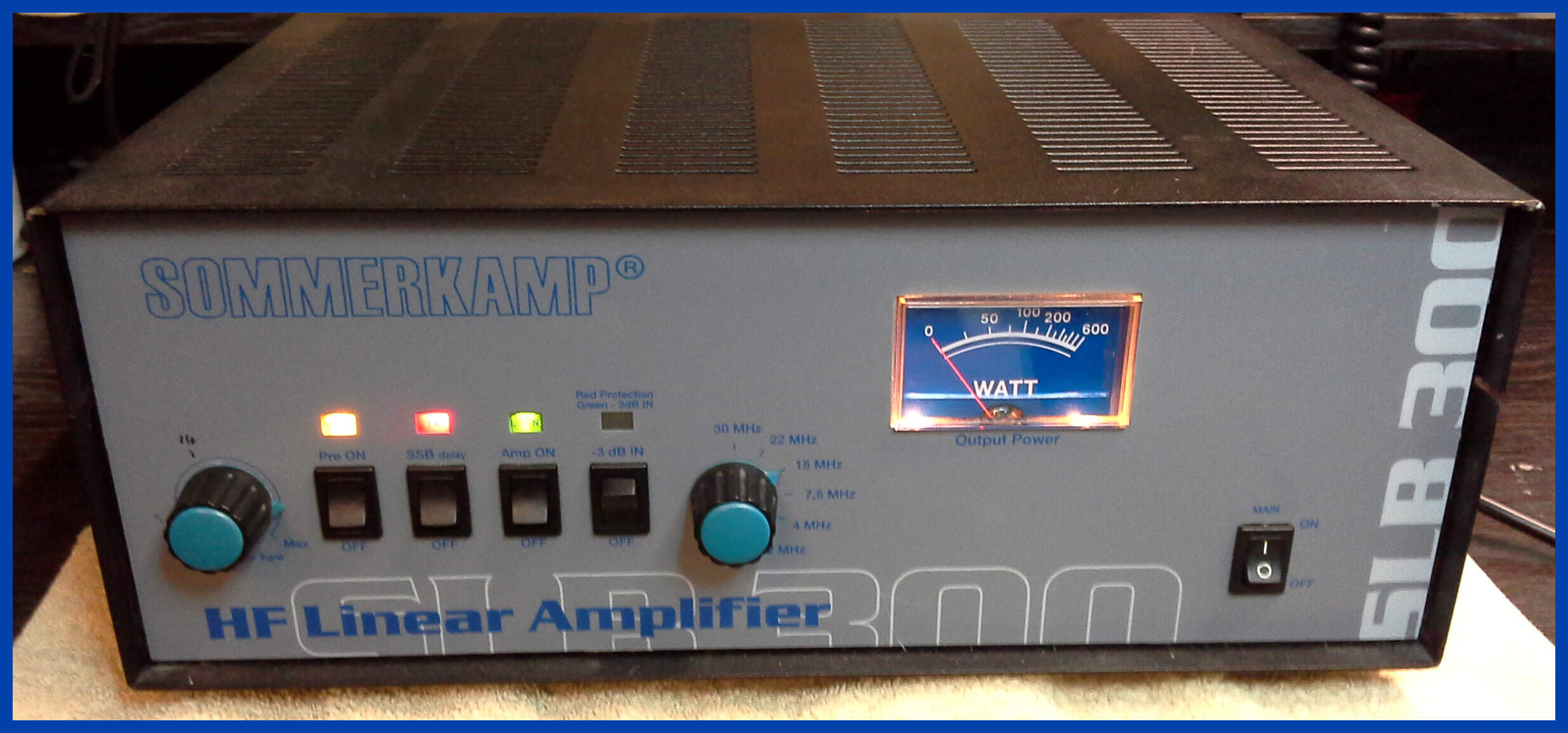
Summerkamp SLB 300
This is a nice example of the Summerkamp SLB 300 HF power amplifier, it produces with a maximum input of 10 Watts an output of 200 Watts carrier (FM), and 500 Watts Peak envelope power on a two-tone single sideband transmission (SSB).
The amp came in with a common problem with transistors amplifiers being that the transistors had blown.
Summerkamp SLB 300
The above picture shows the replacement power transistors installed in the Summerkamp SLB 300.
Summerkamp SLB 300 Power Test
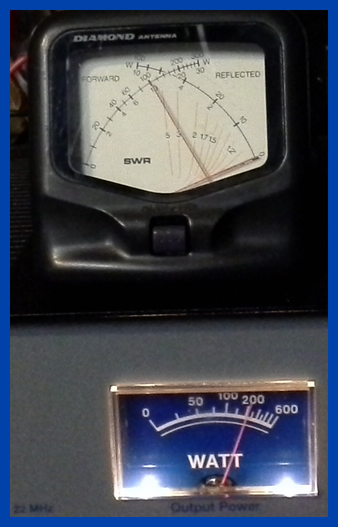
The above picture shows the SLB 300 amp being tested in operating mode with an FM drive signal.
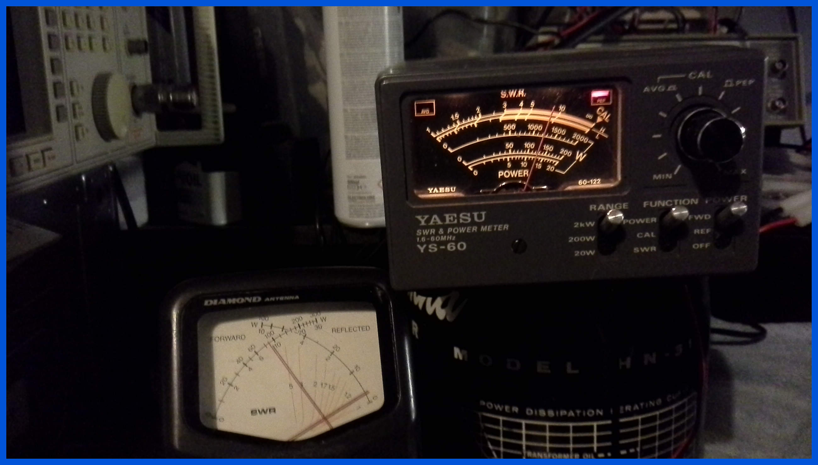
The power meter on the top of the unit is measuring drive power of 10 Watts, and the meter on the front of Amp is showing 200 Watts output power been driven into a 50 Ohm dummy load.
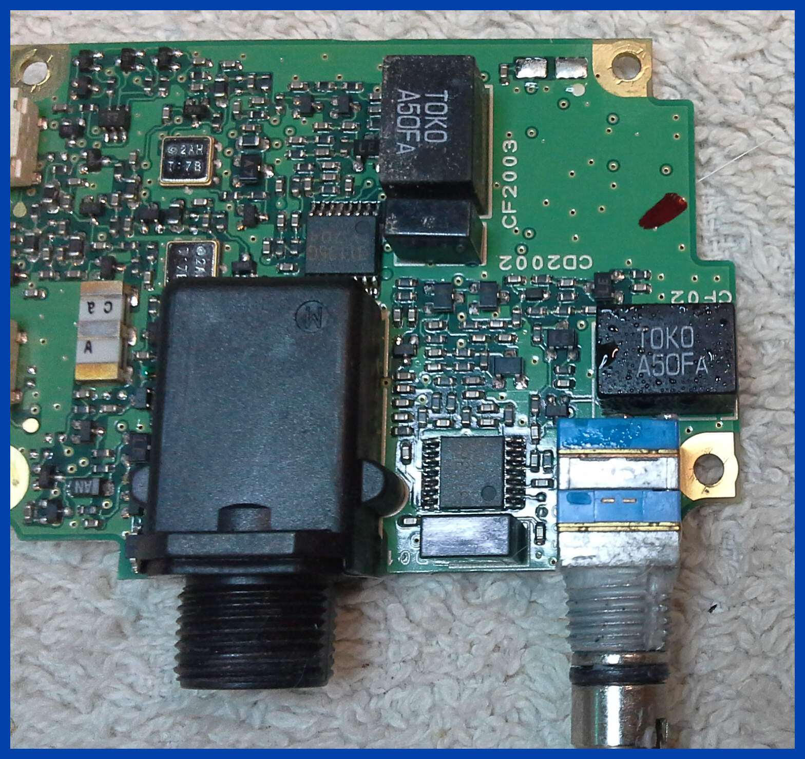
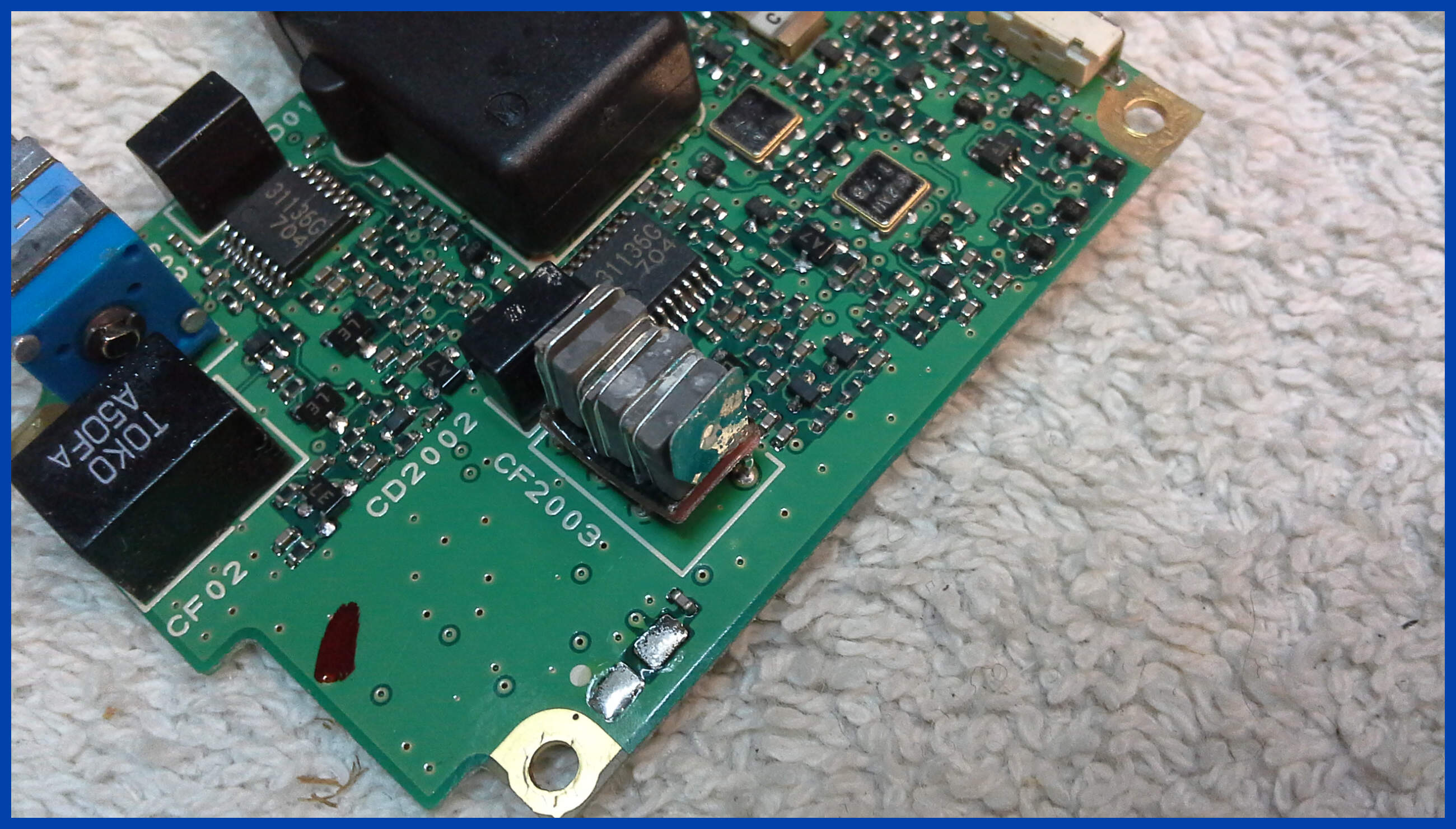
TOKO IF Filters
These filters were used in Kenwood and Yaesu amateur radio equipment.
A common symptom of these filters failing is lack of receiver sensitivity.
A visual inspection of the filters which will either look wet, or have dandruff as can be seen in the picture above, and in the lower picture where I have pulled the cover off you can see the corrosion inside the filter which has stopped it from working.
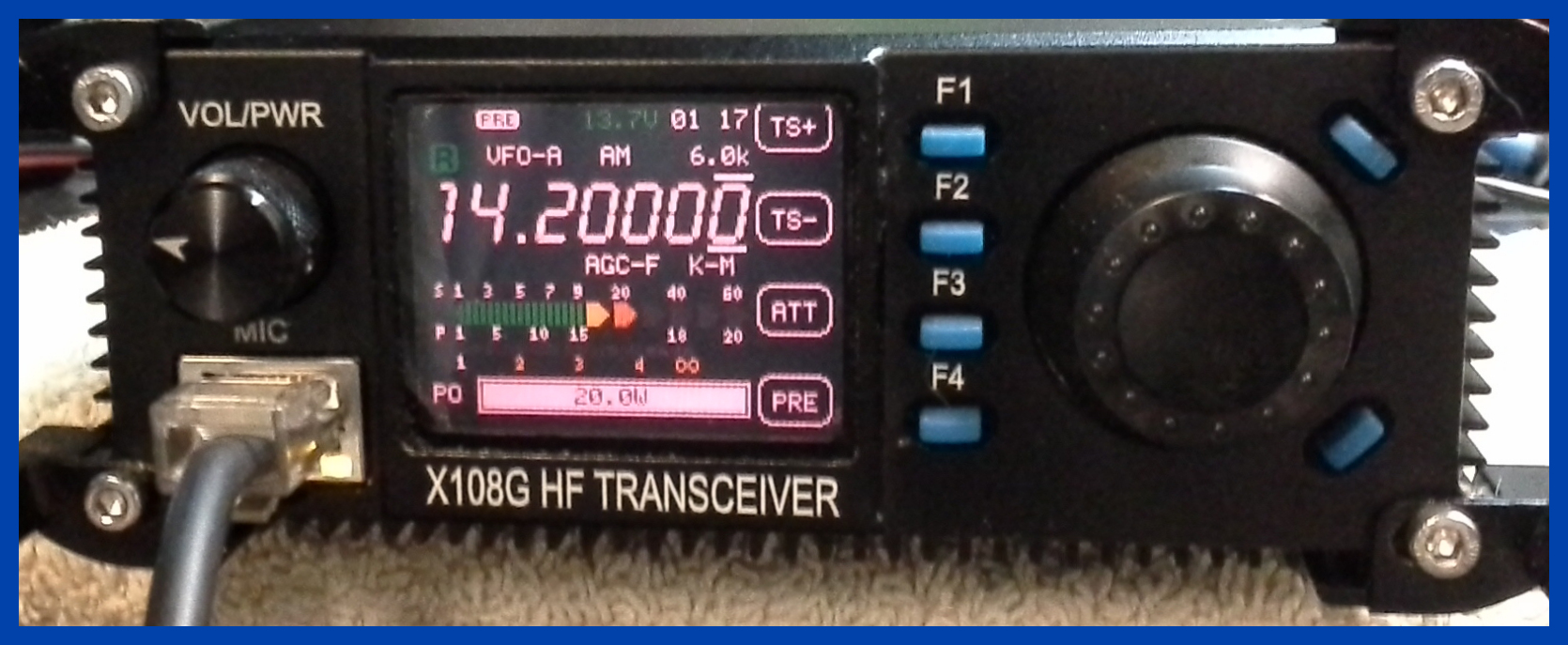
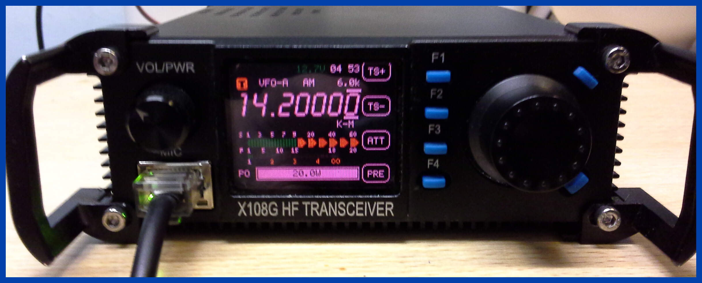
XIEGO - X108G
This radio came in with intermittent transmission, and it was not remembering its last used settings when disconnected from its power supply.
After replacing the rechargeable memory backup battery, and bolting the PA driver board into the radio, its bots had gone missing and was holding on by the board connector.
Intermittent transmission still remained, so I reinstalled the firmware onto the radio and reset the user settings, which cleared the problem.
The top picture of the radio shows the X108g receiving and the picture below it show the X108g transmitting
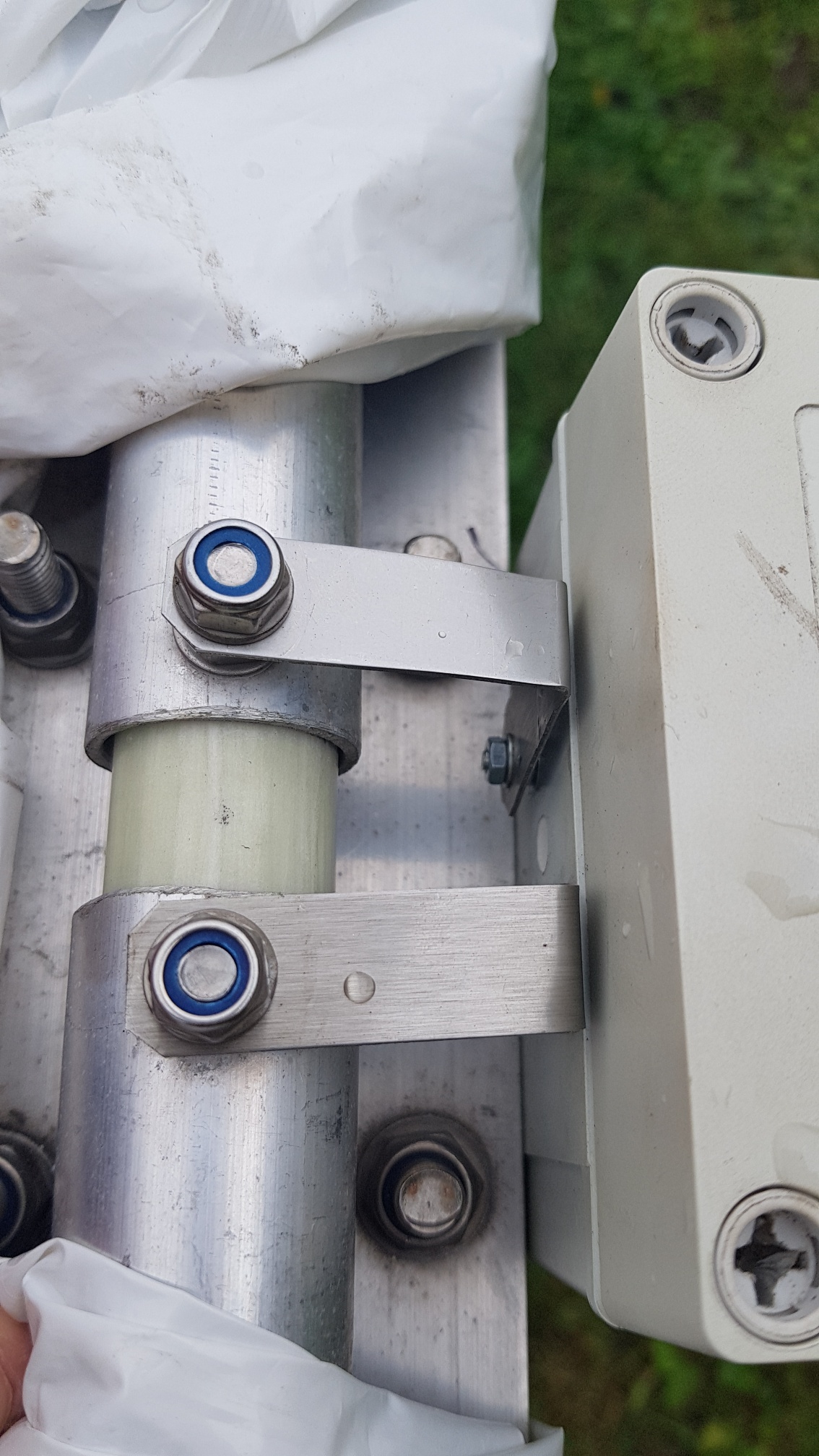
Stainless Steel Brackets
These custom-made Stainless Steel brackets are made especially for the Balun waterproof plastic housing. They are available to buy through us and are made by A G Engineering.
Please phone or text me on the number at the top of the page for further information on how to purchase these brackets.
Related information
I have been repairing radio equipment since the early 80s in the days of the Public Mobile Radio conversion of Pye Westminster’s, and CB radio was in its infancy in this country, I later became interested in Amateur radio, and this lead to my repairing of amateur radio equipment. I specialize in the repair of multimode equipment at component level, with resolving the more difficult problems being what we spend most of our time doing.
We also do a range of radio programming
including the Chinese manufactured range of handhelds, and mobiles; Kenwood
mobiles and recently
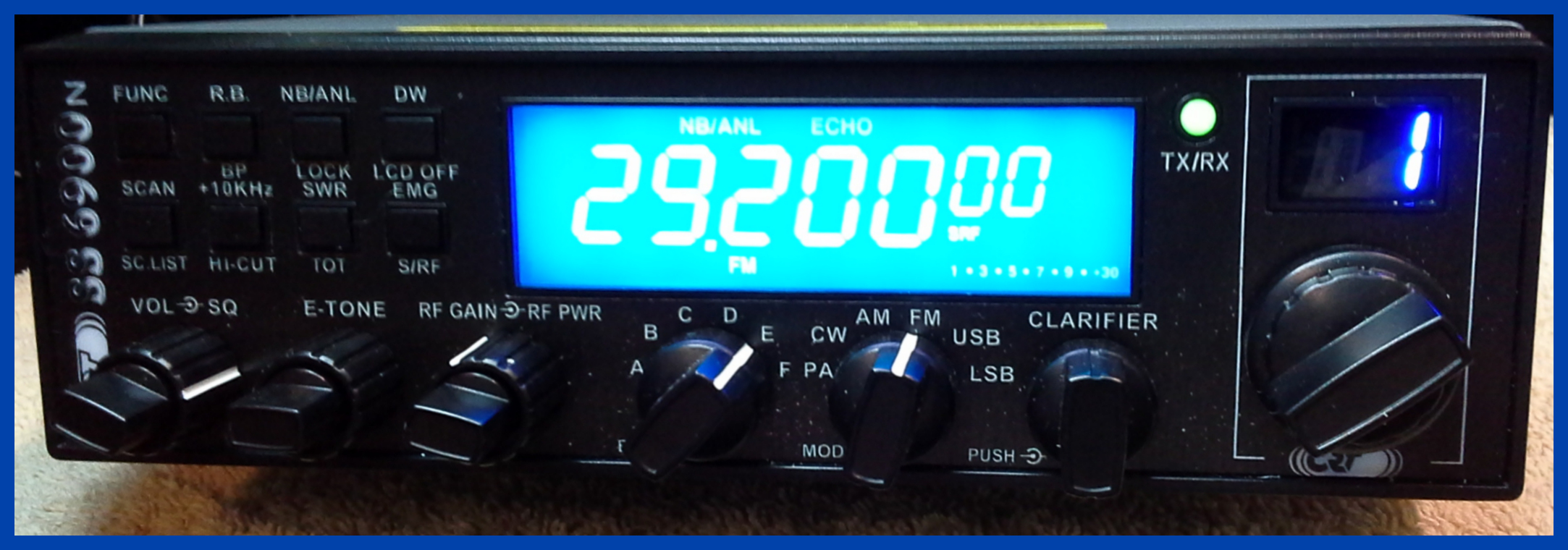
CB Radios including the SS6900.
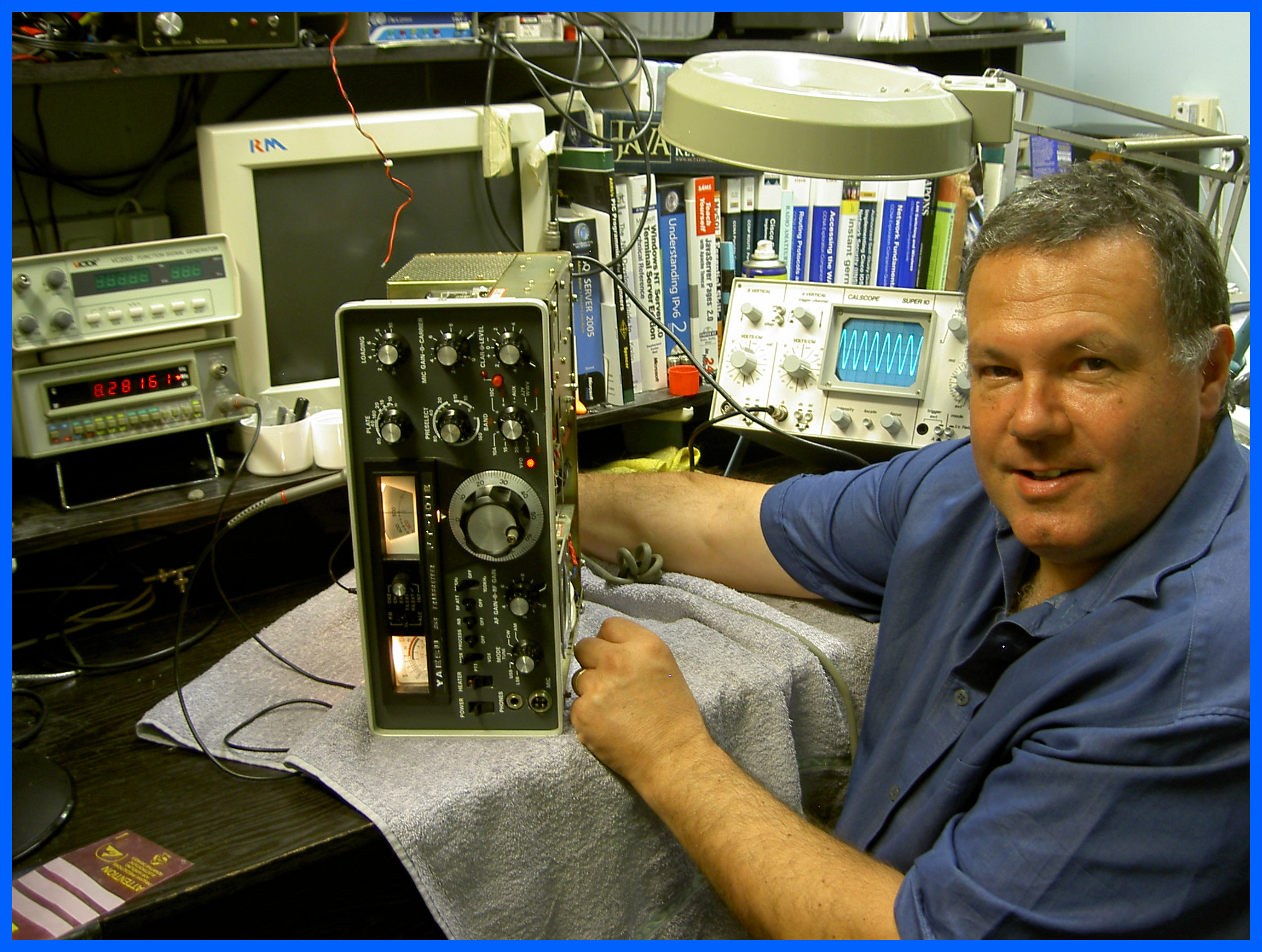
FT101E restoration and repair
A picture of me in my workshop working on a FT101 restoration and repair, which is going well.
Inside of the original Ameritron 3 tube AL 811
HF Power amplifier.
This is the original Ameritron not the MFJ design with Chinese made 811 tubes, so I have put up some pictures for reference of what the Bias Plate and Grid current measures, and the Full output Plate and Grid current measurements; The drive power and input impedance match, and the output power been driven into a 1KW dummy load.
Warning!
Please note that if you are working on one of these amps or power it on with the cover removed, almost everywhere you can touch has a lethal 1.7KV which will kill you if you touch it, and most digital meters if you try and measure it.
Drive Power and Input Impedance
The meter is showing the Drive power into the amplifier just under 40 watts, and the input impedance which is just over 1.1:1.
Maximum Output Power
This is the maximum output power of the amplifier (600W) been driven into a 1 Kilo Watt Dummy load, with oil. Total gain of 15 was higher than expected.
Plate and Grid current at maximum output.
Bias Current while in Operate mode, the Bias Current should be zero if the amp is in Stand By mode.
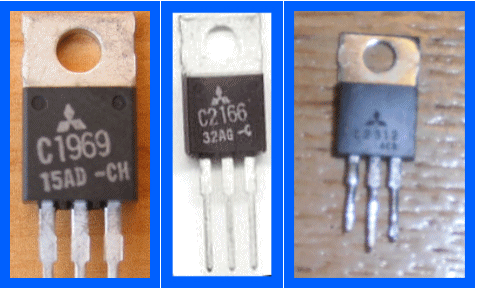
Fake Transistors
We have been receiving a number of radios
with failed Fake 2SC1969, 2SC2166, and 2SC2312 transistors installed into them;
these transistors work intermittently for a short period of time giving a power
output of about 1 Watt and then failed causing no RF power output.
The 2SC2166 had the bias pot turned all the way up putting 2.5v across the Base-Emitter junction was not conducting Collector Emitter and still measured correctly when I removed and tested it when clearly it should have been blown.
If the printing on the transistor is of poor quality, not straight, and to small to read then it's going to be a poor quality probably Fake transistor.
Fake transistors current gain
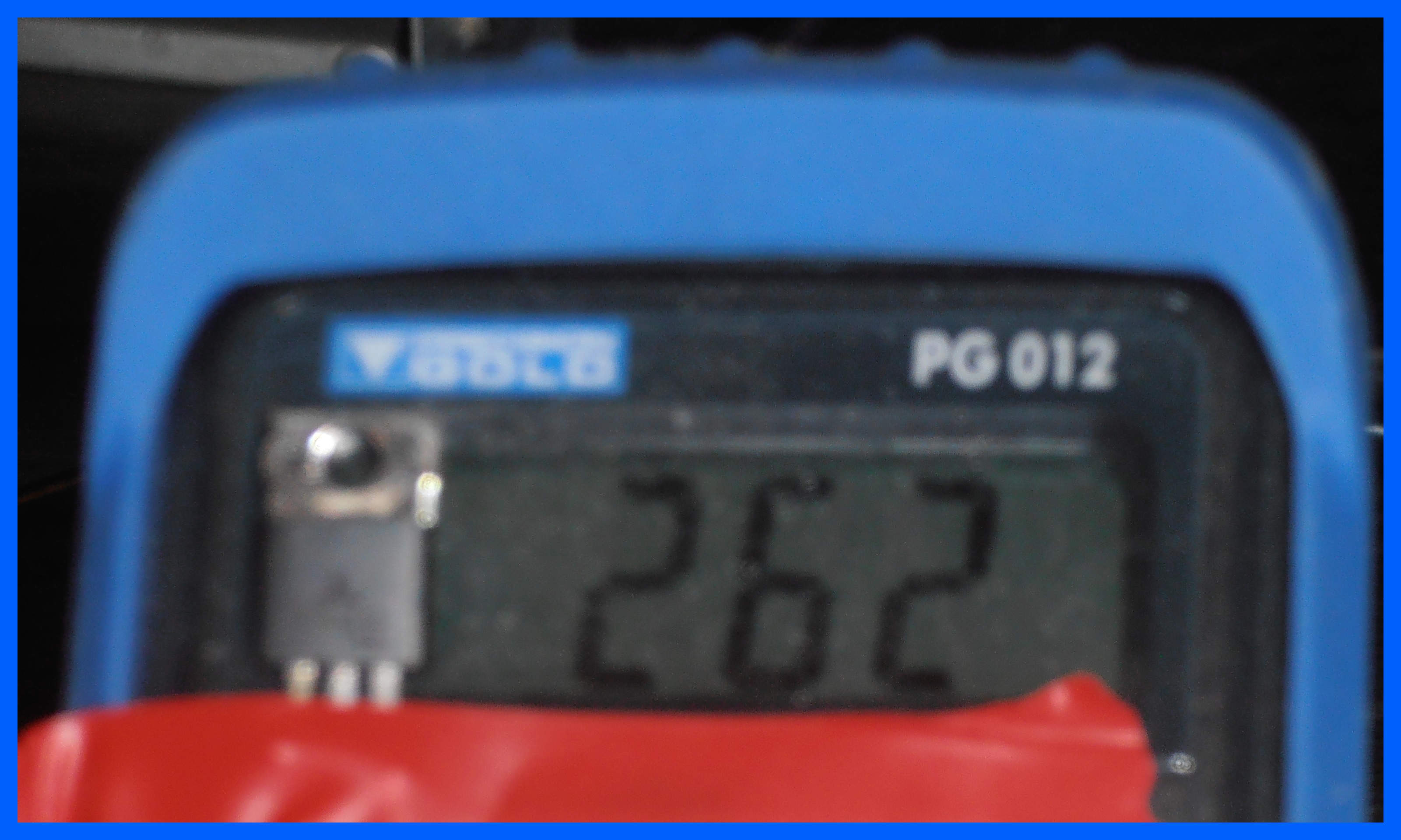
Another indication that your RF transistor is Fake is seen if you measure the Current Gain (hFE) on a transistor tester.
For
the 2SC2312 the data sheet states the best current gain is 90-180 with the “DD”
ident, but you will normally see the 55-110 ident “CC” with a measured gain
around the 90-105 in used transistors found in CB and Amateur Radio equipment.
The Fake 2SC2312 transistor shown above has a current gain of 262 which is just impossible for this RF Power transistor; clearly whatever is inside the package this is not a 2SC2312 transistor and is more likely to be an audio power transistor which is just going to get hot and not produce a lot of power at RF frequencies.
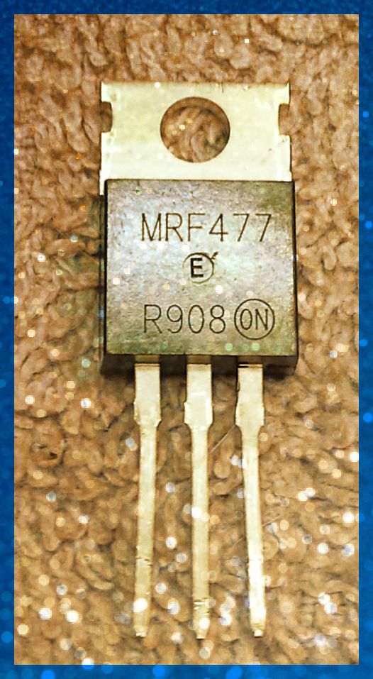
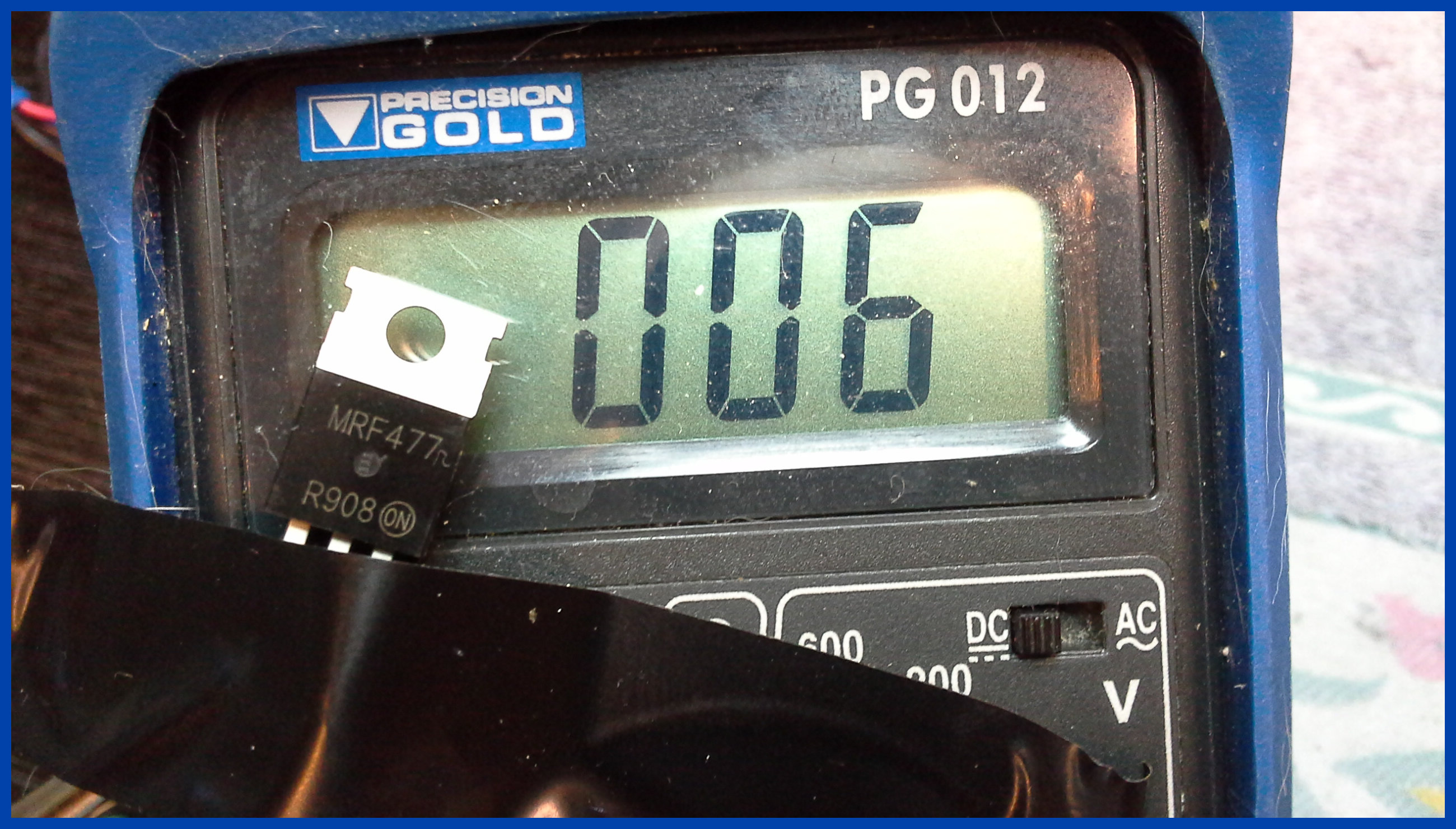
MRF 477
This transistor is not what it claims to be because it should have a minimum gain of 20, and a typical gain of 70 according to the data sheet; this one has a gain of 6.
It is meant to have been made by ON semiconductor, but they have never made an MRF 477.
I also notice that a lot of the transistors I see that don't work or produce very little power output all have a letter "E" inside a circle in the centre of them.
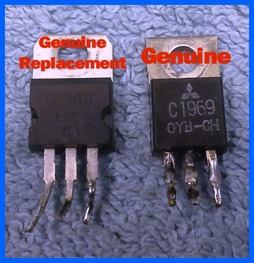
Genuine Mitsubishi Power Transistors
I have written a lot about fake transistors, so I have taken the time to pull two genuine transistors out of my radios so you can see what the transistors look like, the key things to look for on the Mitsubishi is the “CH” which is the current gain (Hfe) of the transistor, and comes in “A-D” followed by “H” with C being the most common. The date number 99 or 0 for the year 1999/2000; remember they were not made after 2006 so a date of 15 is impossible on the original Mitsubishi transistors.Failed Capacitors
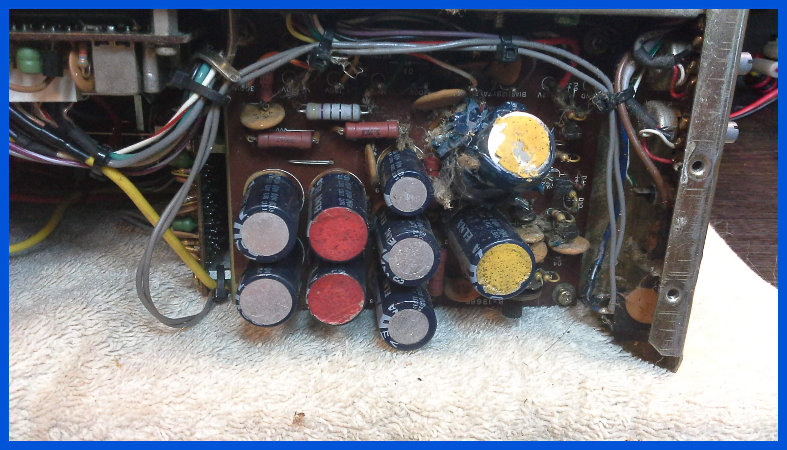
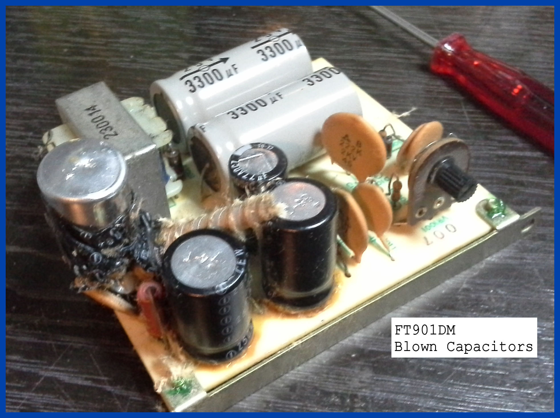
Failed Capacitors can let go at any time, and in rather a spectacular manner which is why you need to get your radio service regularly to avoid this happening.
You will notice that the Capacitor from the FT901 has a dent in the top case which occurred when it exploded and slammed into the regulator board which is located in front of it shorting out its circuitry.
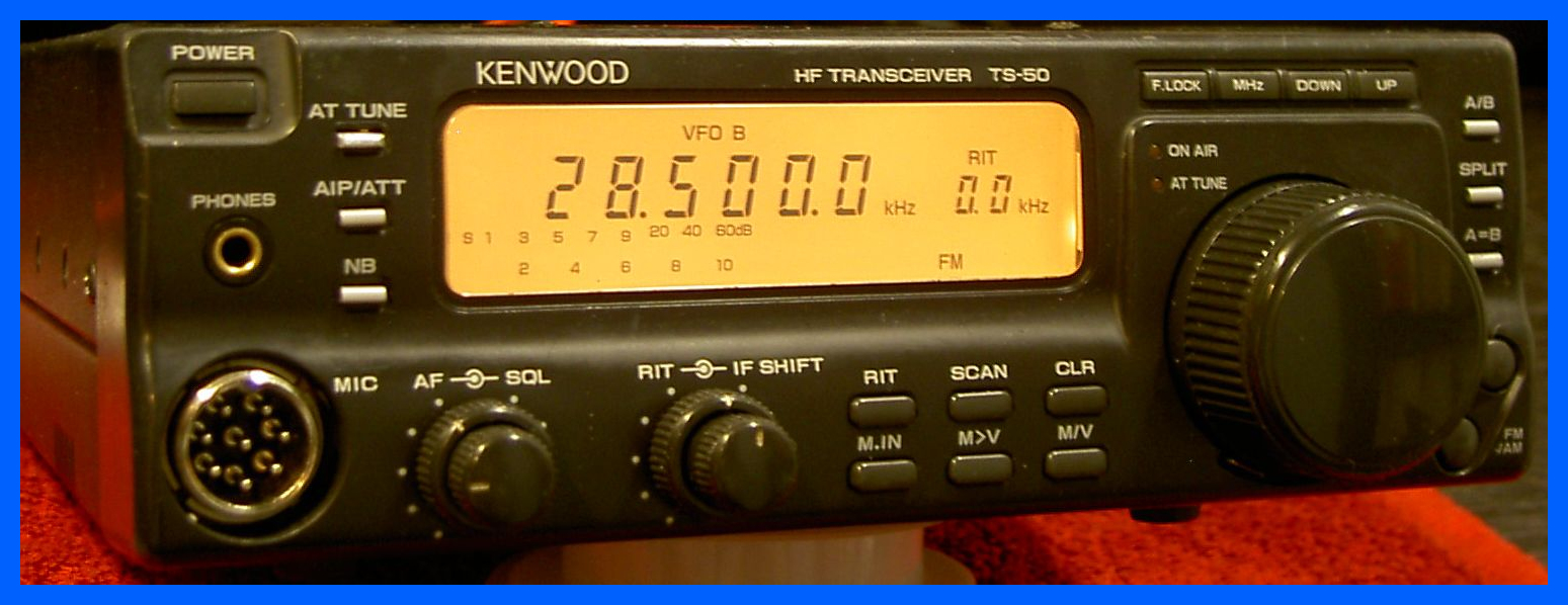
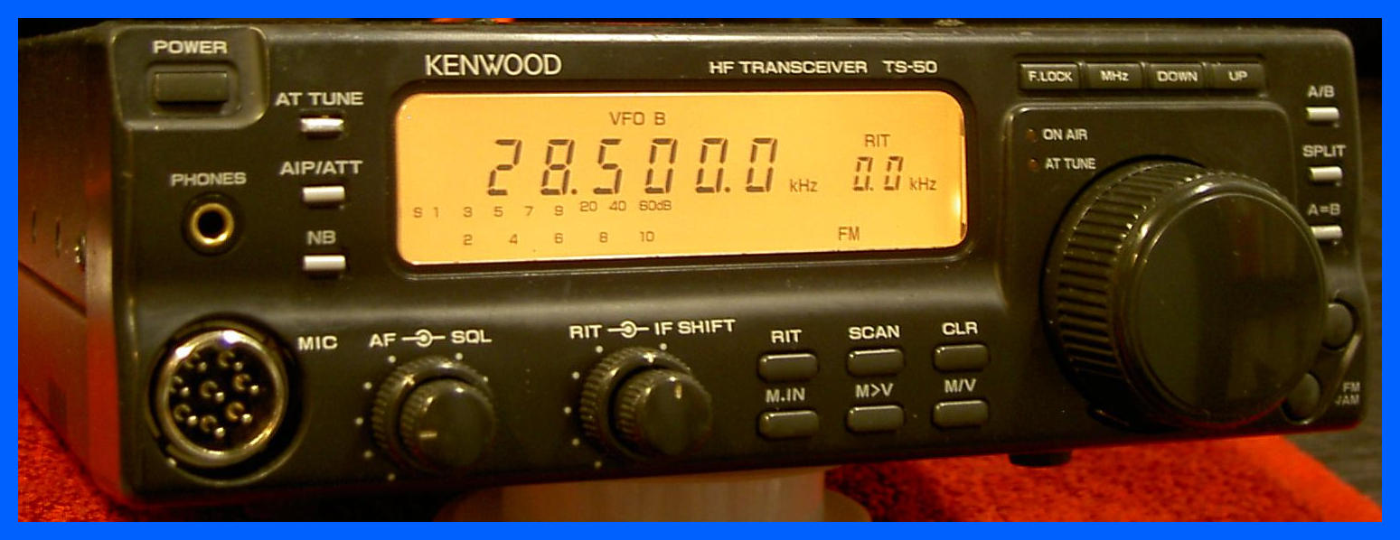
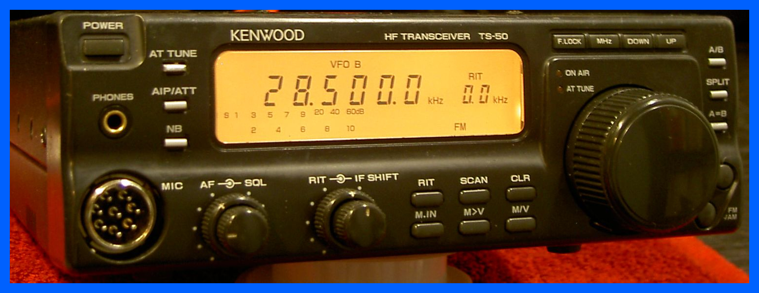
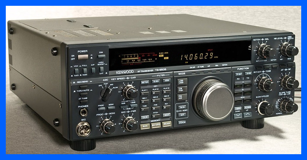
Kenwood TS 50
This second Kenwood TS50s I have seen in the last few
years in the workshop, when they are working they are a very good example of
small mobile Amateur radio HF transceiver.
Unfortunately by the time that I get to see them they tend to be very much
worse for wear; the first one I repaired had 34 separate faults spread across
the whole of the radio, fortunately the radio had not been screwdrivered so it
was just a matter of finding the failed components and replacing them.
You have to be aware of fake Chinese components for these radios because they
just don’t work, and this is an all surface mount radio so unless you're happy
with a hot air re-workstation and a fine tipped soldering iron working on these
should be left to the professionals.
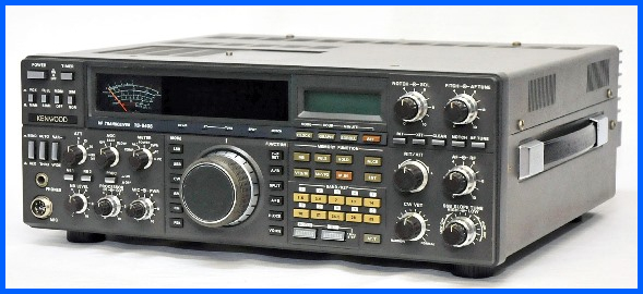
Kenwood TS-940S
This came in with the reported “dots” on the Display which is the PLL out of lock problem, but when I took the radio cover off the power supply had completely blown all of its components off the board in into the radio. The power supply boards are no longer available ether new or on the second hand market so decided to completely rebuild the power supply from scratch. This repair took over a year with having to source some of the components internationally and for the components that are no longer available finding equivalents components that were still available. Once the power supply was operational I found that the fan control circuit had failed so a rebuild of the fan control circuit, a service of the fan itself and I lowered the fan turn on temperature to 30 °C to help to keep the radio cool. I moved on to repairing the negative voltage inverter which had also stopped working.
The TS 940 also needs it bulbs changing from time to
time, as well as the backup batteries for the Clock and the Micro processor,
and a modification to the AGC circuit if the meter (Pegs) slams hard onto the
end stops when you turn the radio on and off.
Kenwood TS 850
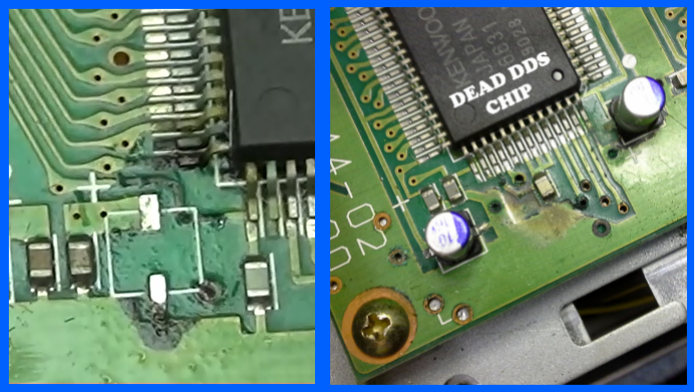
I have been repairing a few TS850’s, all of which have had leaking capacitors on the DDS board and other problems on the DDS board unrelated to the leaking of the capacitors.
I am very good at getting the surface mount capacitors off the board without ripping the track off, but you still have the problem of repairing the corrosive damage that has been caused and if you are really unluckily the DDS chips themselves which also fail if the acid shorts them out.
The IF filters have failed in a few of the radios I have repaired as well, and the Transmit/Receive switching can from time to time can burn out for no obvious reason.
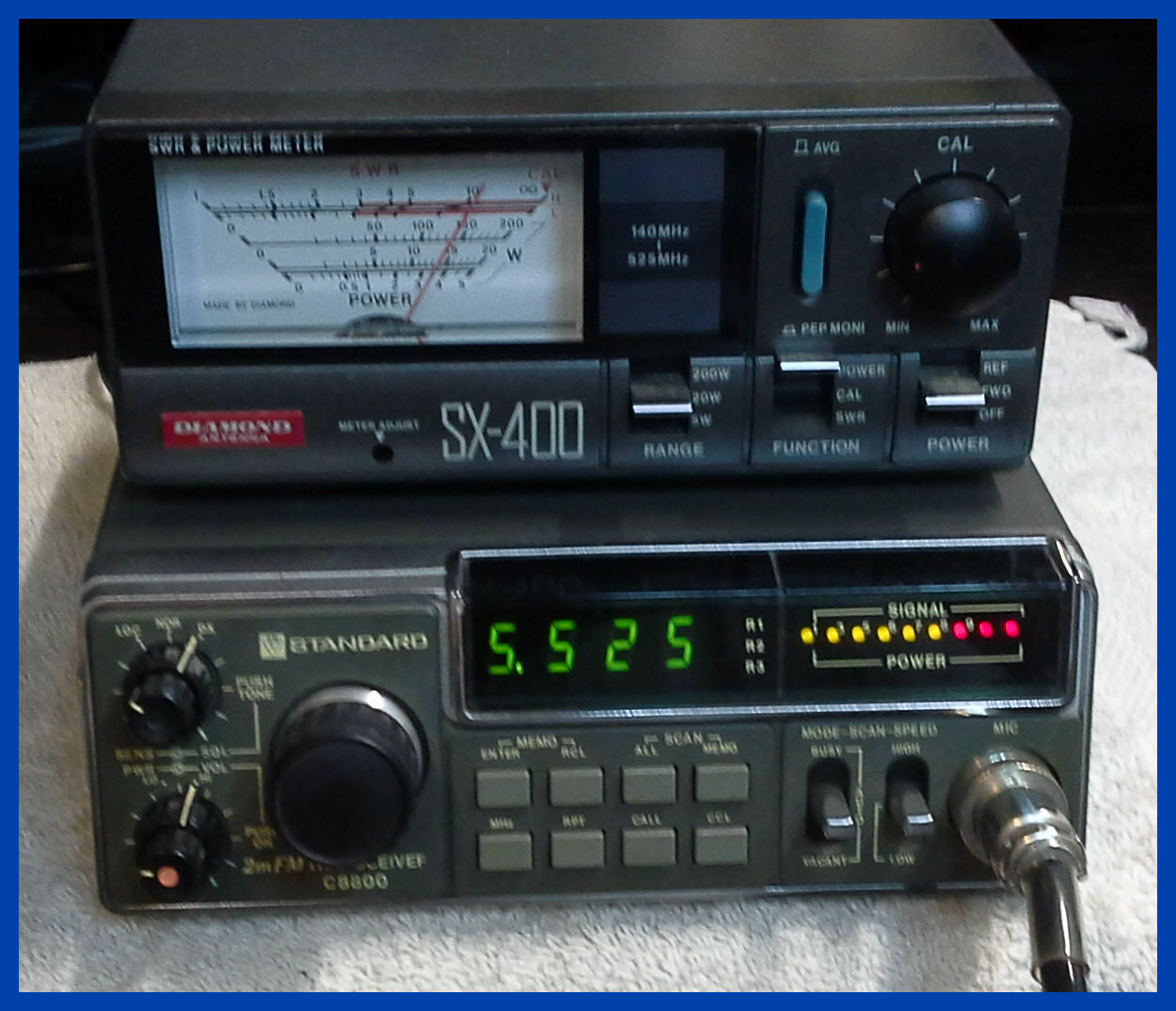
Standard C8800
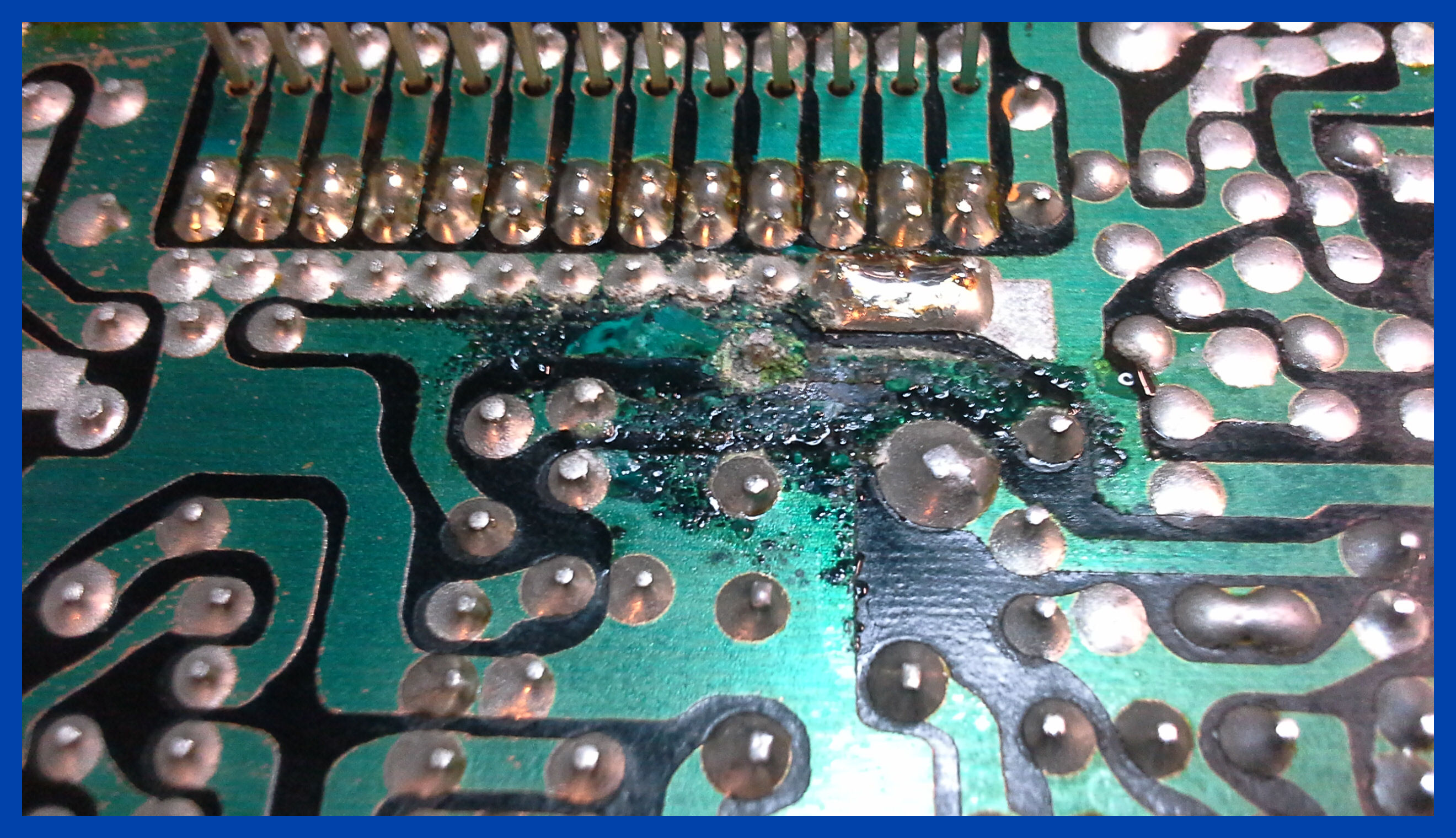
The picture above shows what happens when the electrolytic capacitors leak onto the printed circuit board or a radio transceiver.
The bubbling you can see is your copper tracking been eaten away and once you clean it up you will find you have no tracking any more.
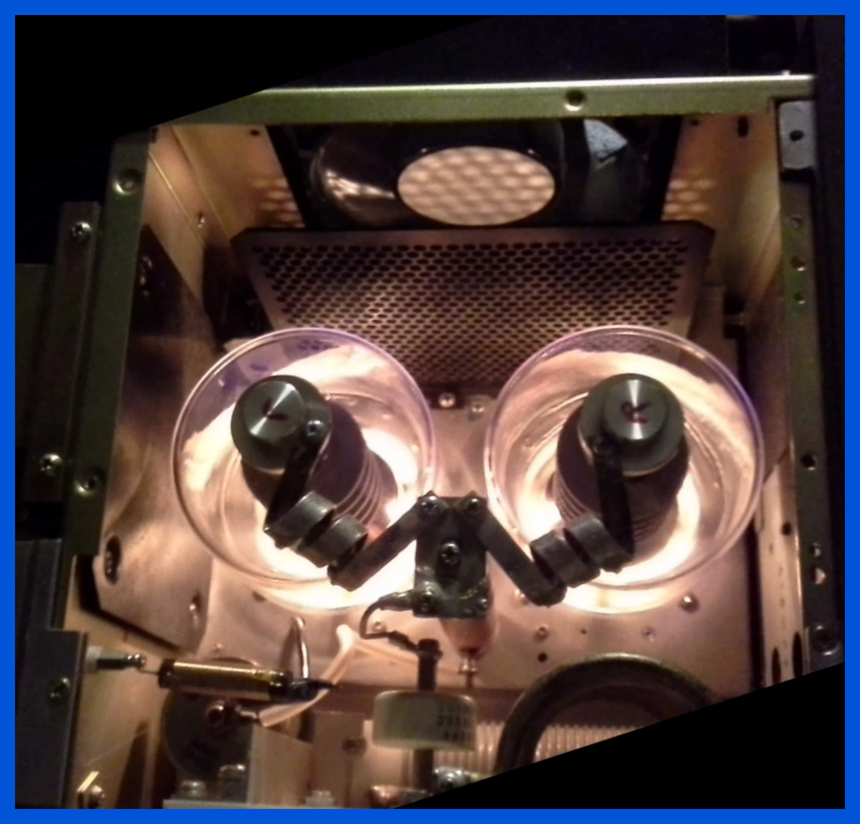
Kenwood Tl-922
During the winter nights there is nothing better to look at than the warm glow of a pair of 3-500ZG with the higher plate dissipation the plate doesn’t glow red when you are transmitting.
Please don’t try this at home; several of the safety features have been removed to allow me to take this picture, and the 3.2KV on the top of the valves will kill you if you touch them.
Kenwood Tl-922
The picture above shows the final amplifier test into an oil filled Cantenna dummy load.
Kenwood TS 120S
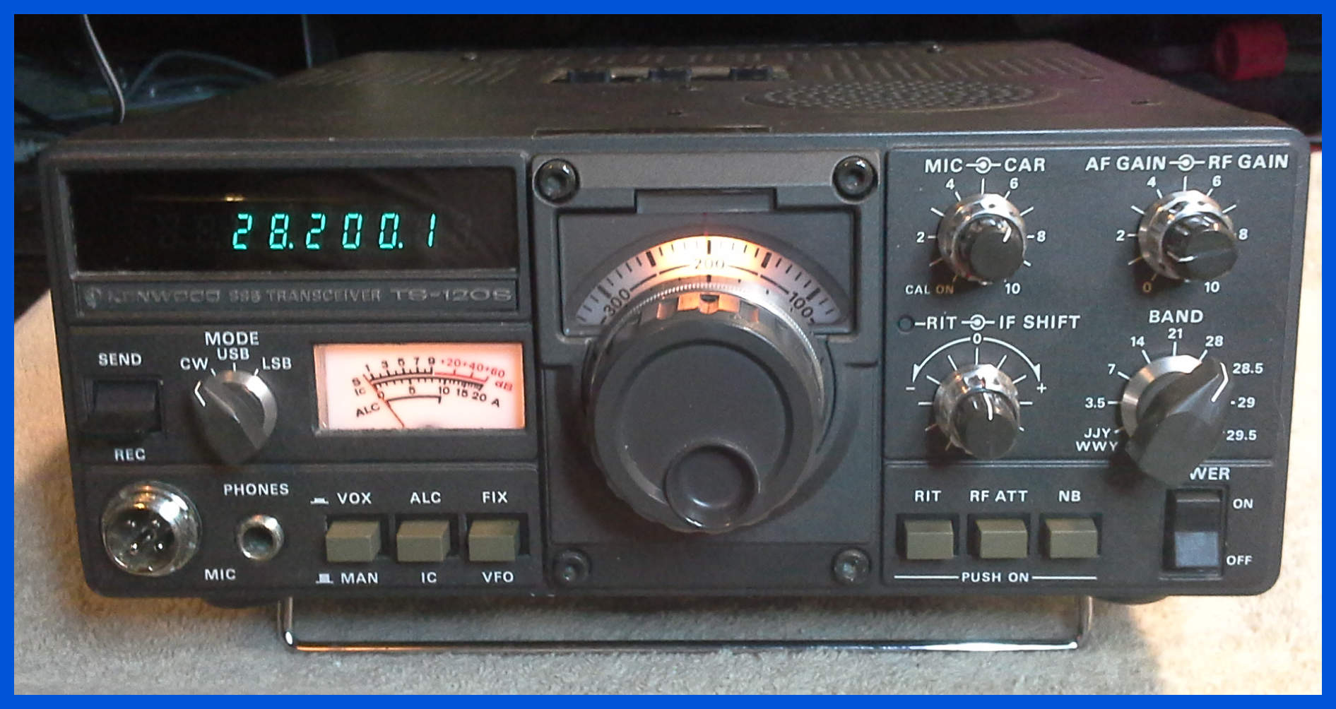
This radio came in with a reported problem of being rather deaf, after some TLC it is now up and running.
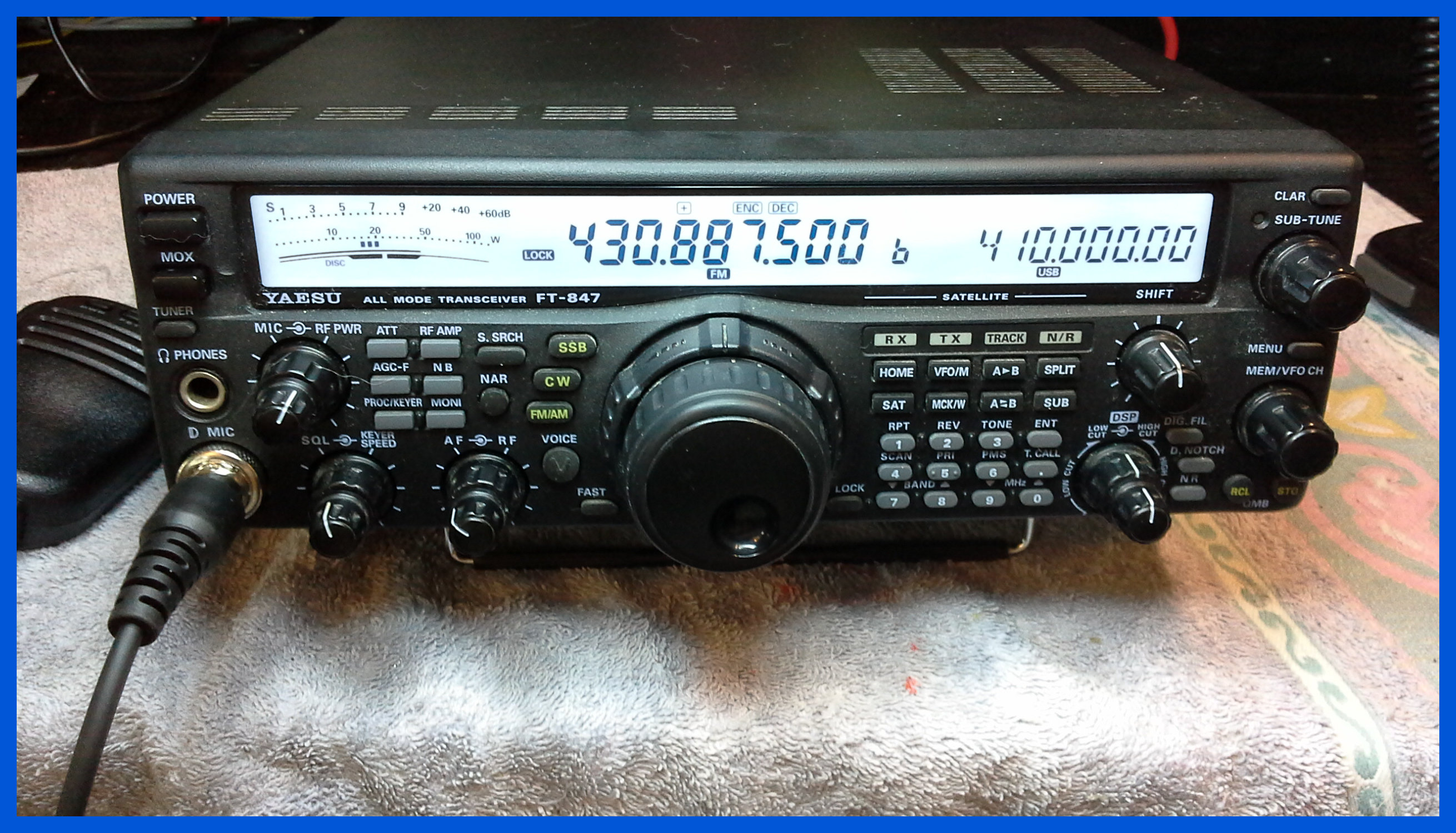
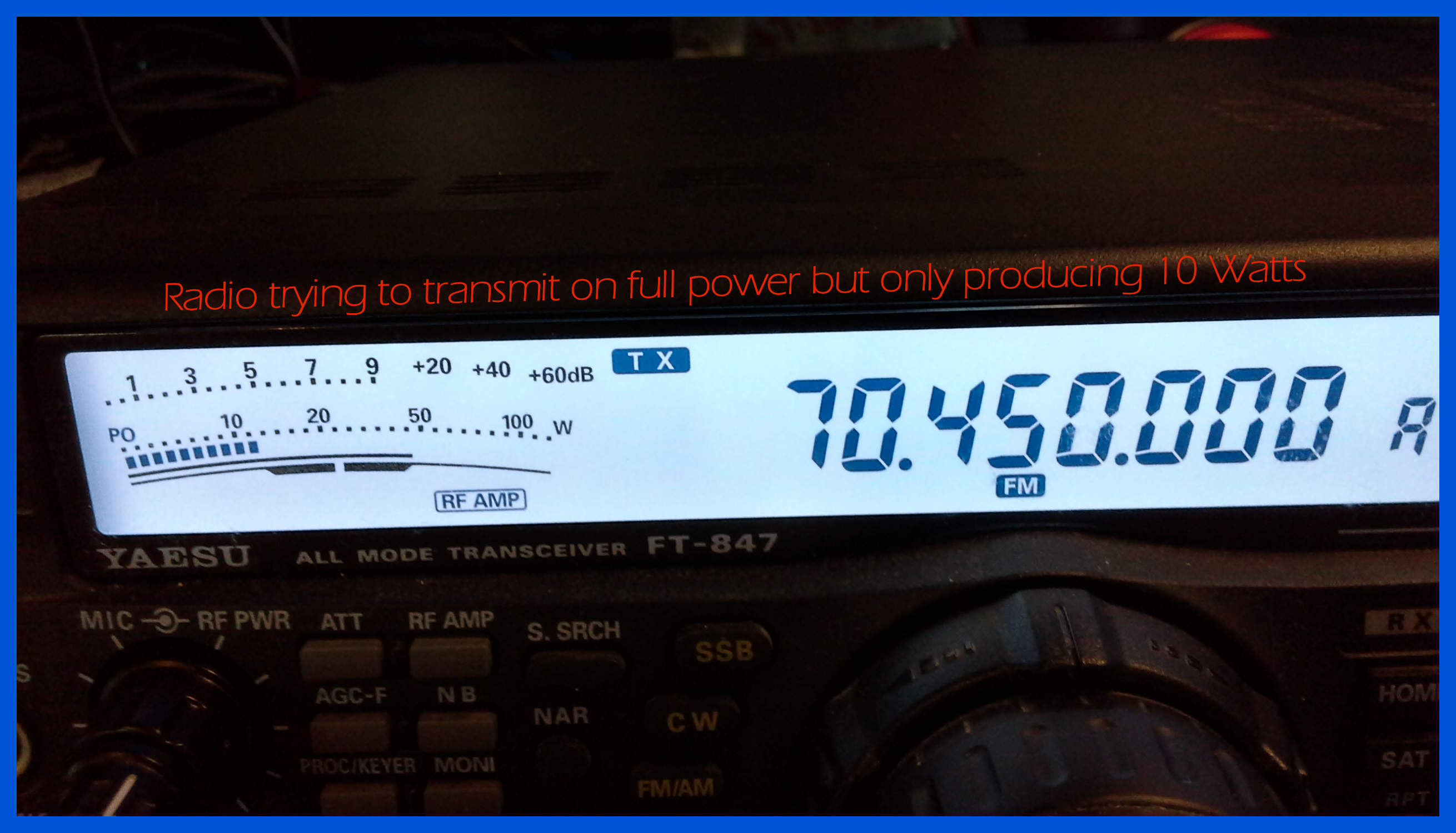
Yaesu FT 847
This is an HF/6M/2M/70cm transceiver, which works very well out of the box; it is different from other radios of its type having an antenna socket for each of the groups of bands. The picture above shows me testing the radio on my local 70 Centimetre repeater.
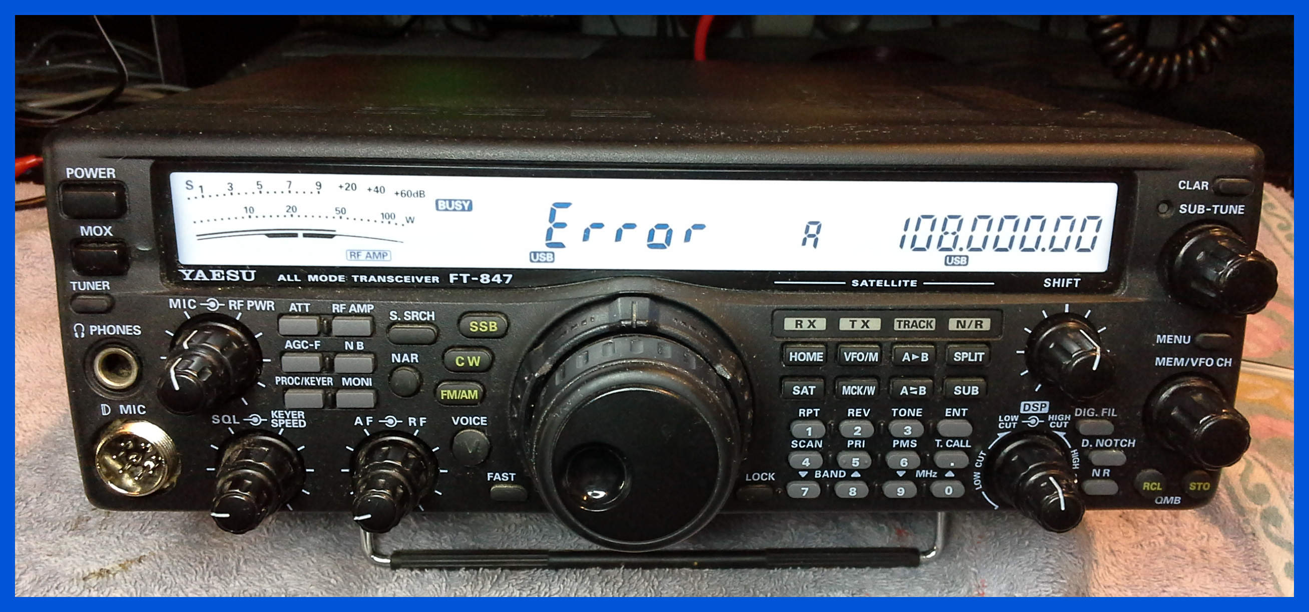
The picture shown above shows what happens if you get the wideband settings wrong, or remove some components from around the CPU you get this display even if you have reset the CPU.
I have read a lot about what radios can or can’t do after they have been wide banded, and to be clear just because you can get the radio to tune to a frequency it may be happy to receive on that frequency but there is a good possibility that it will be very unhappy trying to transmit, as is shown in the picture above the 70MHz band which uses the 50MHz (6 Meter) low pass filter will receive without any problems, but only transmits 10 Watt on full power which should be closer to 100 Watts.
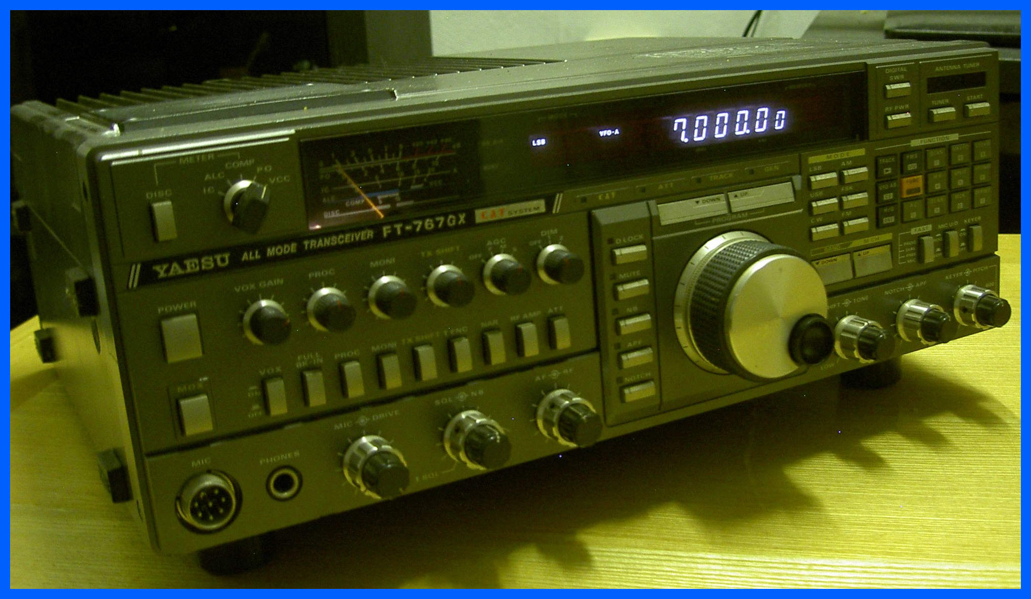
Yaesu FT 767GX
This is a FT767GX with the 2 meter and 70 centimetre modules installed in it; It has taken a few weeks to identify why the ATU was
not tuning at all, and the SWR wondered about while it was enabled, and the
modules in the back reported to be transmitting 10 Watts but in fact they were
only producing 1-2 Watts.
This radio also suffers with the switching diodes failing
causing also of interesting faults, the cooling fans go noisy and need
servicing, and the main tuning stops travelling in any direction when the
tuning knob is turned.
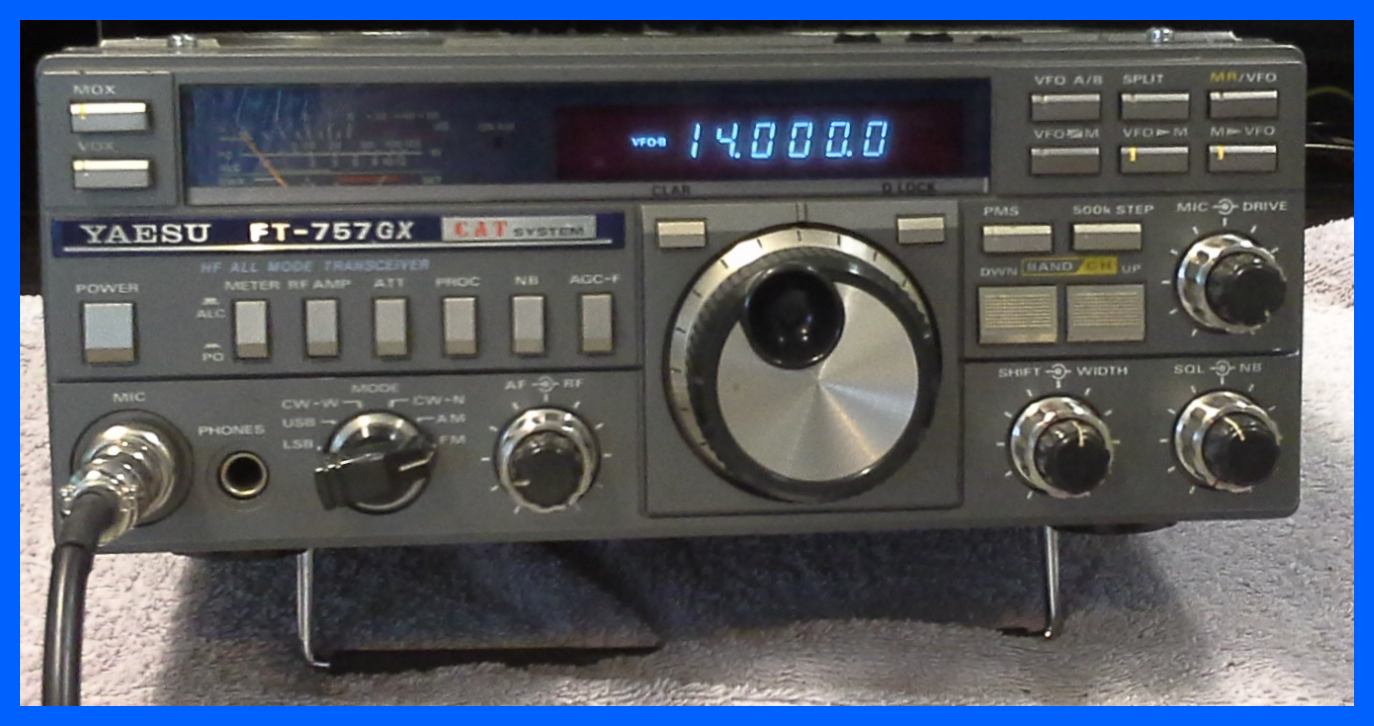
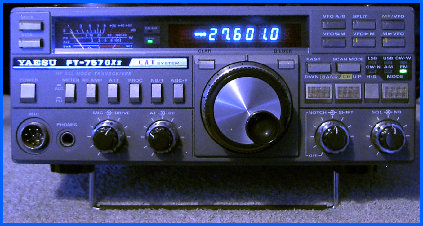
Yaesu FT 757GX II
I have been having a lot of new faults with the FT767/757 radios I have been looking at recently, problems with the Phase Locked Loops (PLL) going out of lock, and mixer components failing. This 757 came in with a collection of strange faults including cracking on AM, No transmission on any band or any mode, and the meter lamps had failed. This is of course a complete departure from the well documented diode failure these radios suffered from in the early days.
Yaesu FT 757
I have spent a lot of time repairing the Yaesu FT 767
radios, and one day a FT 757 turned up for repair, it had No Receive, No
Transmit, and No noise out on FM.
After inspecting the radio I discovered that something very strange had
happened to this radio, with the Transmit and Receive 8v supplies being present
in both transmit and receive, the switching diodes had also gone, but I
expected that this is a common problem with the FT 757 modes of radio.
A collection of additional components had been found on the bottom of the board
RF Board, and PA Board but didn’t appear to perform any useful function and so
they were removed and the radio was restored to factory defaults.
Some thirty separate faults later and being realigned because someone with a
screwdriver had had a go as well this radio is again up and running.
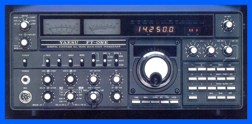
Yaesu FT-One
A 1982 Yaesu HF Set which turned out to be one of the longest repairs I have ever taken on, this radio was not transmitting the full amount of power expected and worse still was not operating on the same frequency as displayed on the frequency readout and it also changed as you changed modes as well.
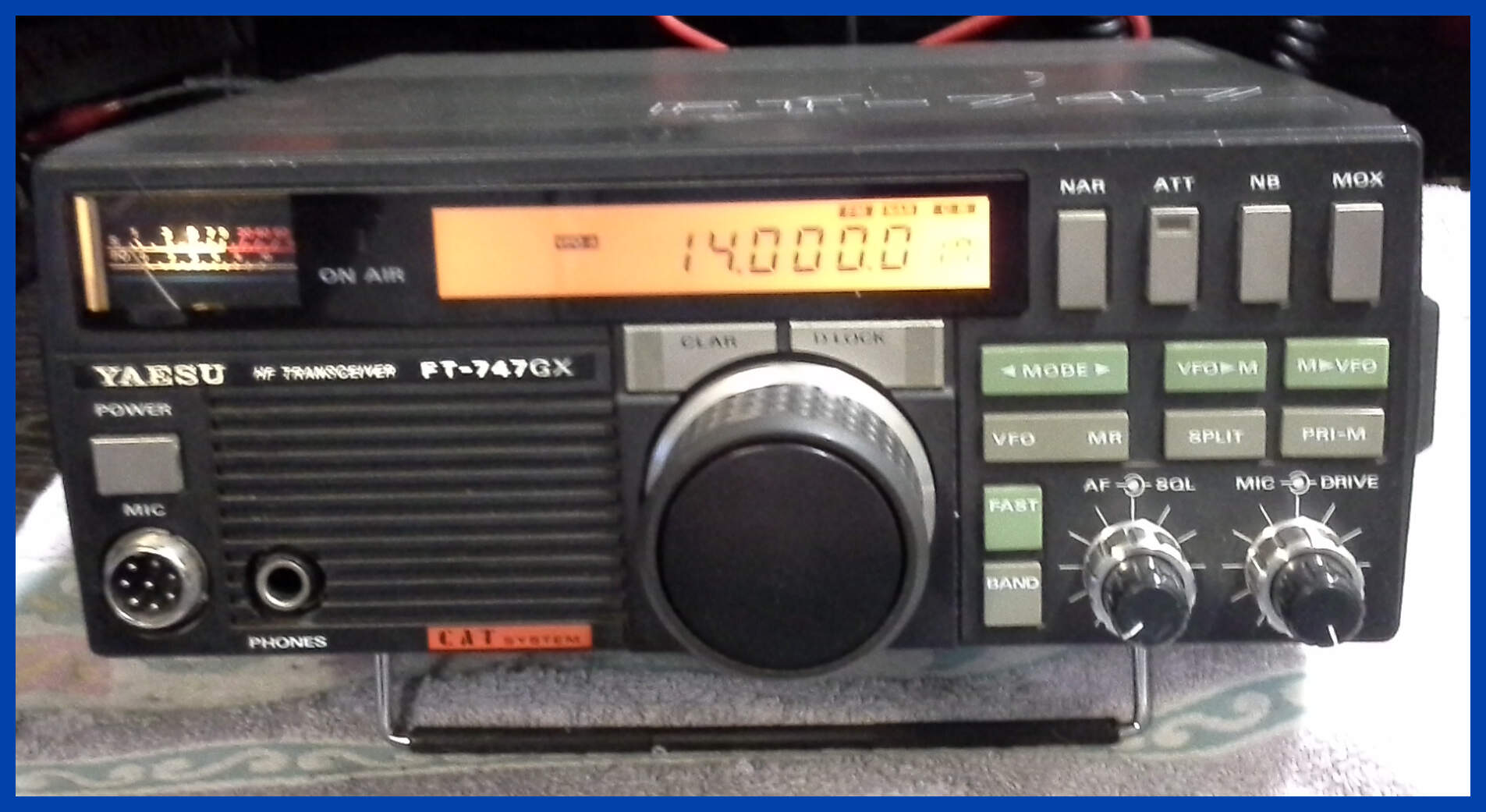
Yaesu FT747GX
This radio was off-frequency and the main tuning control was so worn that it jumped all over the place.
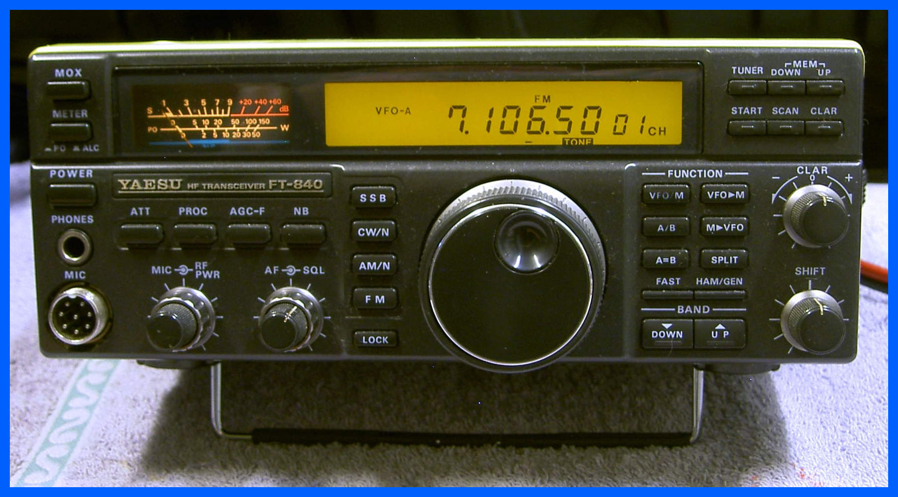
Yaesu FT 840
This radio came in with a flashing LCD, a classic
PLL Out of lock indicator.
The problem was traced to a failed power supply on the Local Board which
included a number of failed electrolytic capacitors, burn tracking and pc
board, and numerous failed solder joints.
After some careful and time-consuming replacement of the failed components and
the repair of the printed circuit the radio was returned to an operating state.
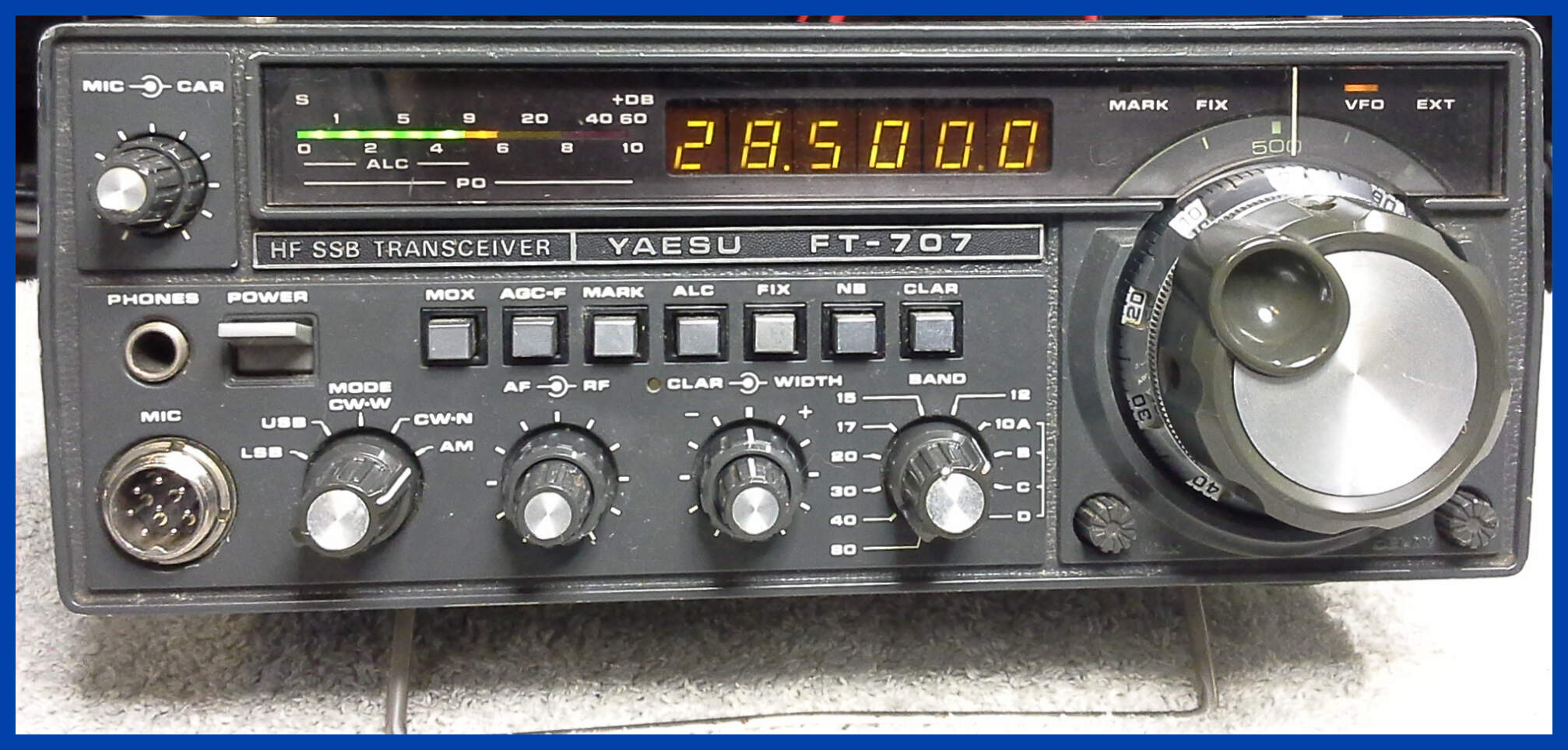
Yaesu FT-707
This radio has received a general repair and test to get it back to a fully operating state.
Yaesu FT-707
This is another FT 707 which has received the replacement of the tantalum capacitors which have a nasty habit of going short and exploding, and while doing a Transmit test thinking I had replaced them all there was a cracker-ling sound and the magic smoke appeared from the PA unit. A tantalum which was not on the circuit diagram had let go, and as you can see from the image above gotten very hot burning the components around it.
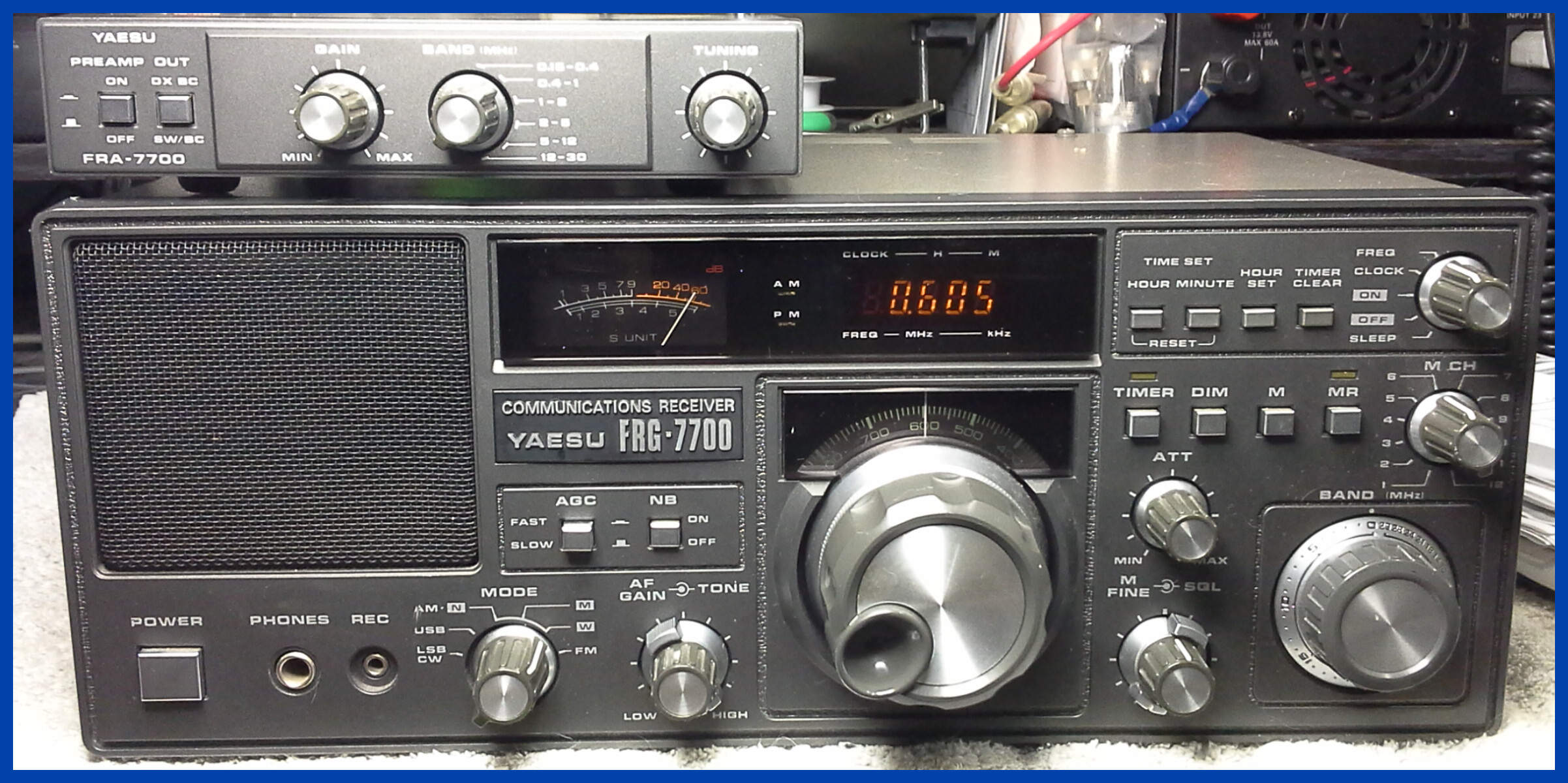
Yaesu FRG 7700
This receiver came in with the normal problems of the band switch not working all the time, and after inspection it was noted the power supply board had burned due to bridge rectifier problems and the PLL was off-frequency. The volume and band switch controls were cleaned, and the receiver board was recapped, which restored the expected performance of this receiver, the power supply and PLL board was recapped to remove some very old capacitors.
The above picture shows the receiver under test listening to the local radio station.
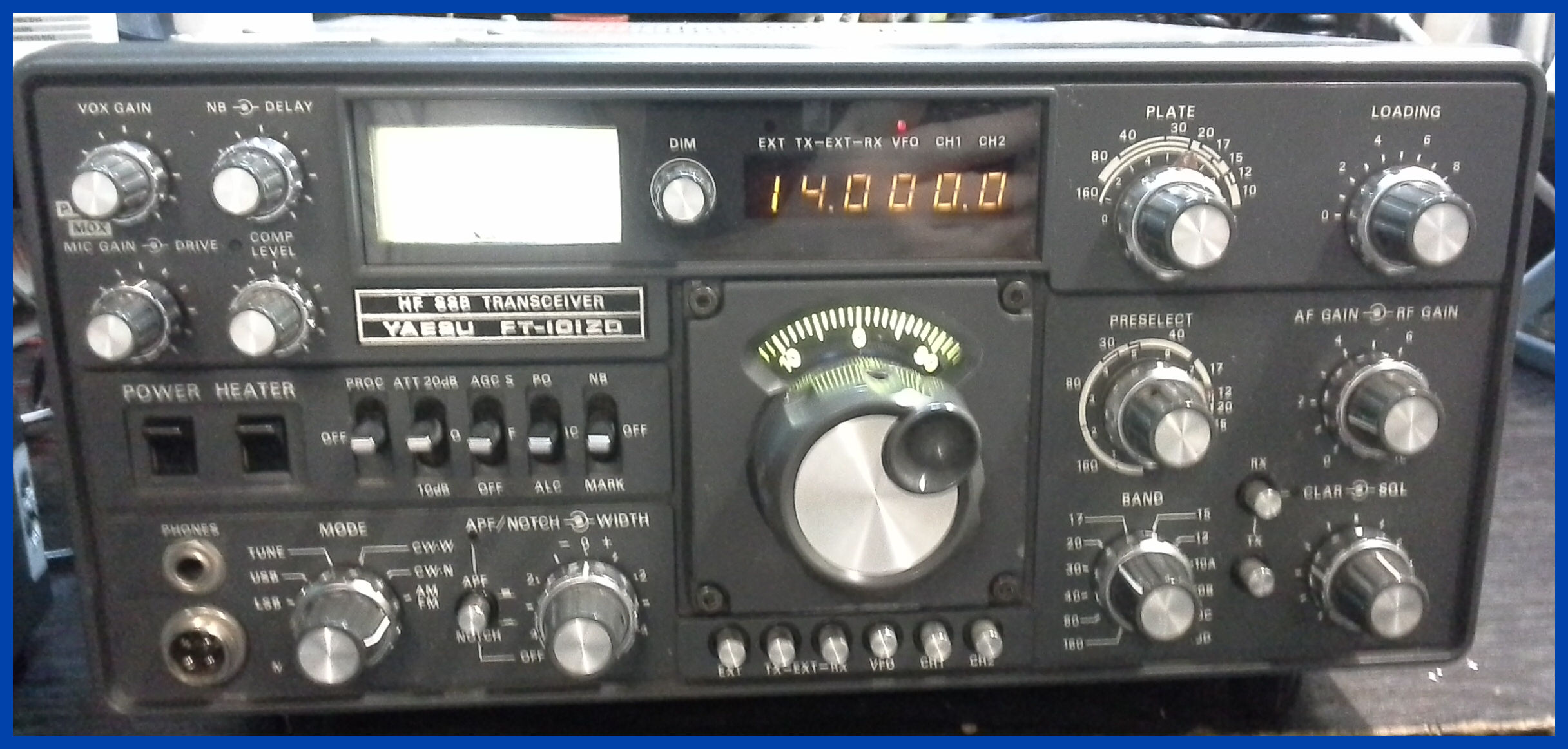
Yaesu FT101ZD
This yaesu came in with exploded high voltage capacitors on the Rect-B board, and very poor transmit and receive performance along with the normal problem of most of the display bulbs had blown.
After a new set of electrolytic capacitors were installed on the Rect-B board, and a problem with the FM board, and RF board was resolved which was causing the loss of TX and RX on all bands.
The radio was tested on transmit and receive, it was found that the ALC circuit also on the Rect-B board had failed as well; being only a small circuit all of its components were replaced and this restored the ALC function.
The power supply voltages were checked to see that they were correct, and the final Bias was set to the correct value; the 6v supply to the VFO was checked for stability.
There is nothing worse than having your radio tune itself up and down the band because the 6v supply is not stable.
The crystal board crystals coils were adjusted so all the
crystals produced the same amplitude; I am not sure if the settings had drifted
over time but some crystals were very low.
Yaesu FT101ZD
This yaesu came in with a note saying it keeps blowing fuses, there were several shorts in the power supply, but unfortunately it was to late, it appears the transformer insulation has gotten hot and leaked out, see the picture above.
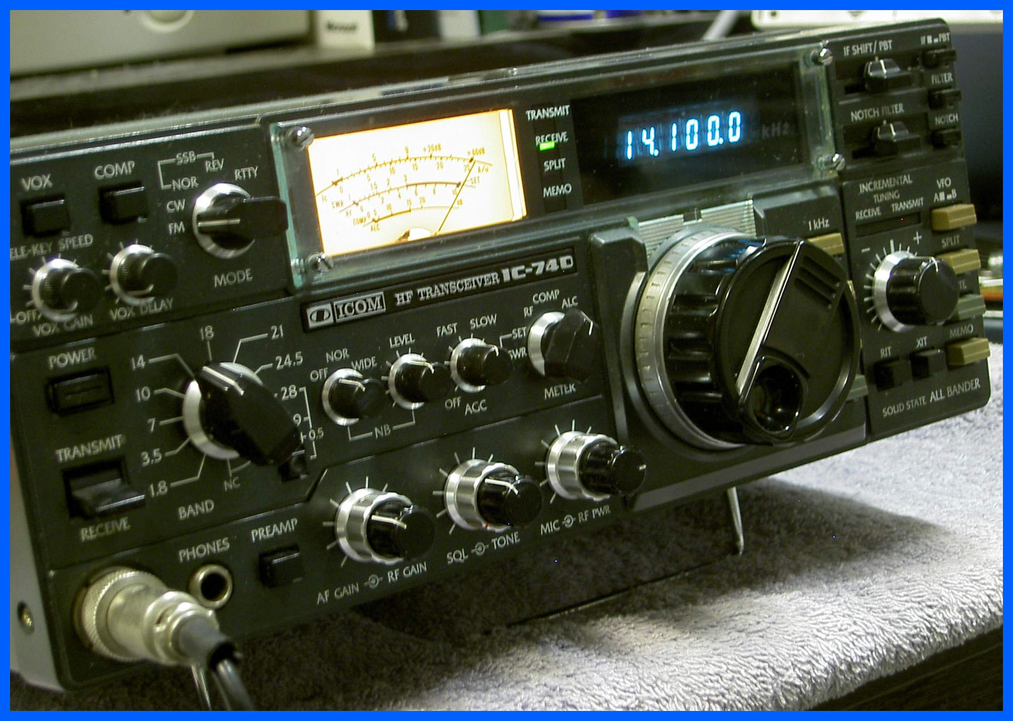
Icom IC-740
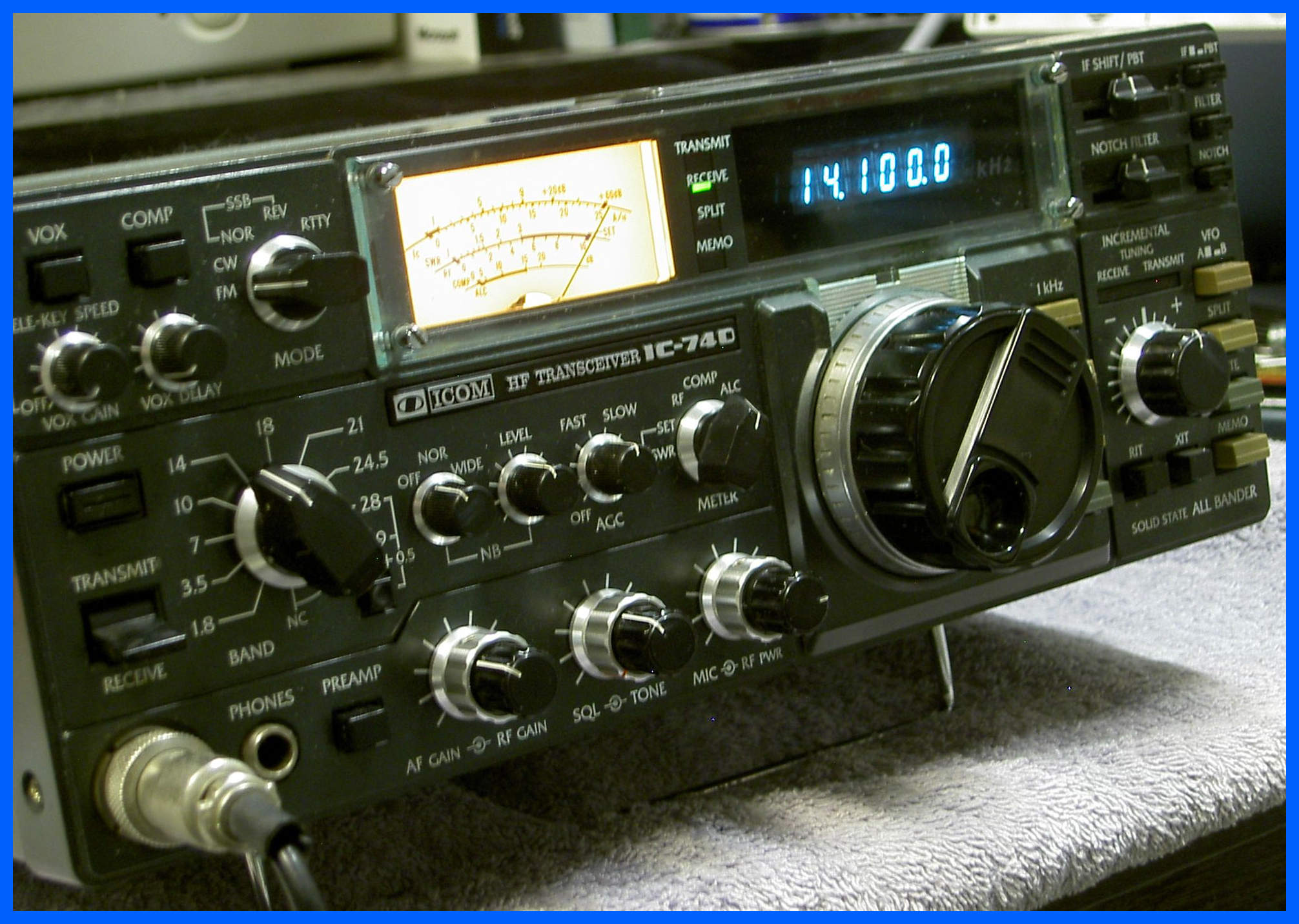
This radio came in without any transmit output power, it was discovered that a number of faults had developed over time, and were successfully repaired after which transmit on all modes was restored. The normal checks were also performed as well as the On-Air test.
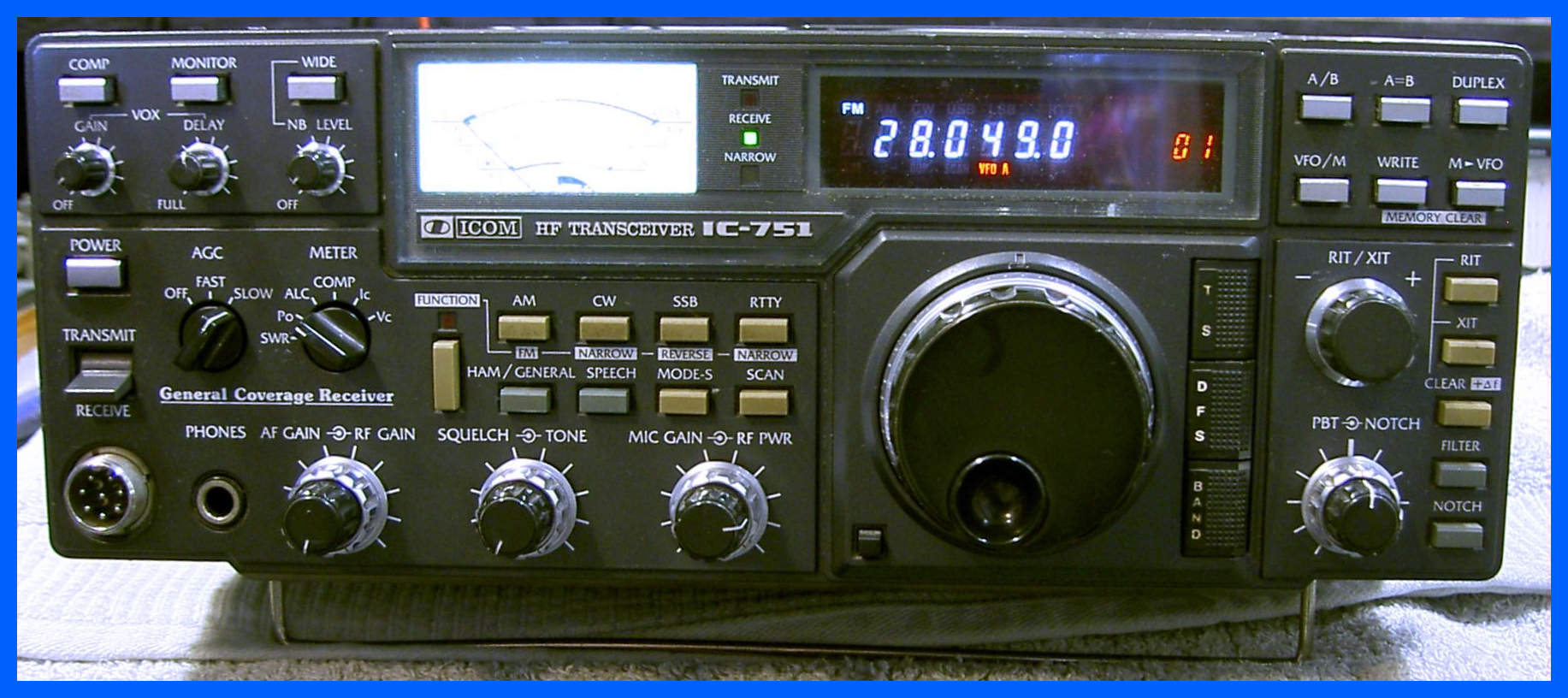
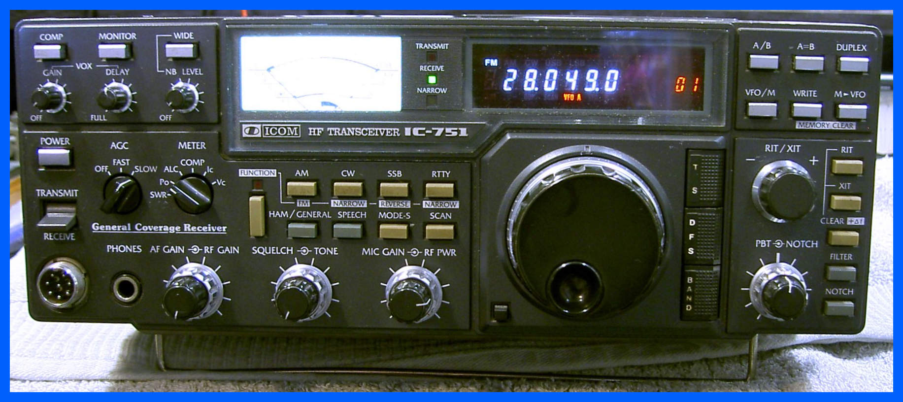
Icom IC-751
This radio came in to the workshop with no display, no receive, and no transmit, and turned out to be one of the longest repairs I have undertaken. It initially looked like the battery had gone flat which is a common problem with these radios, but it turned out to be loads of problems with various internal power supplies, and the PLL was also out of lock. The finishing touch to this repair was a new meter high brightness LED, and some new screws in the top case cover.
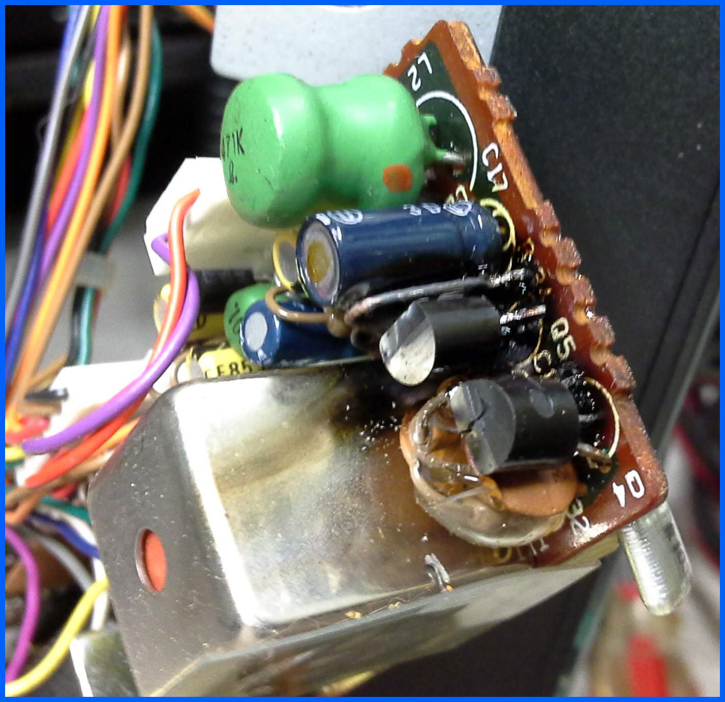
IC 745 Inverter
This small circuit powers the display in the front of the radio, it does have a habit of stopping working and I have repair quite a few of these circuits, but this one has let go in rather a spectacular manor, with Q4 splitting down the middle, and some burnt tracking on the bottom of the board.
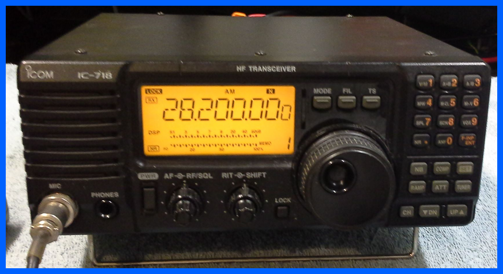
Icom IC718
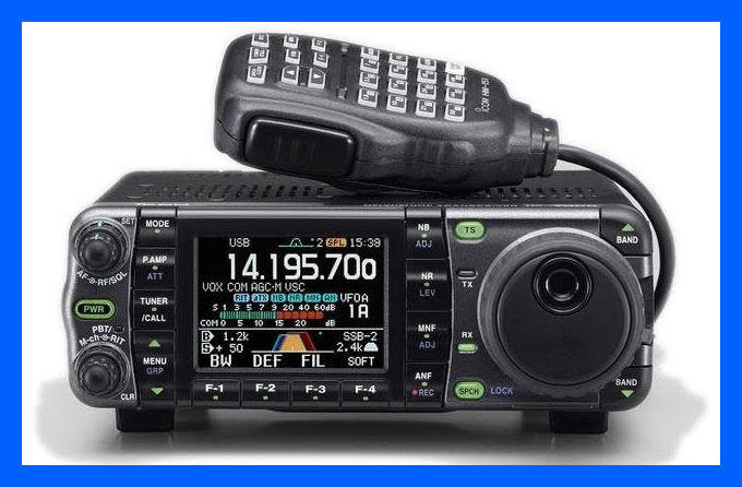
A friend called in to have me fit his CR-338 high stability crystal into his Icom HF radio.
Icom IC-810
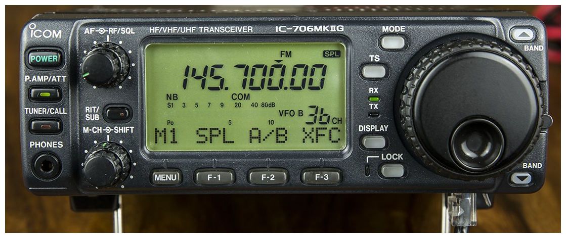
This is the second visit of this radio, it came in several years ago with the standard no transmit on 70cm’s but this time had no receive.
Like so many of the problems with these ageing radio's capacitor failure is the root cause of the failure and once replaced normal service is resumed.
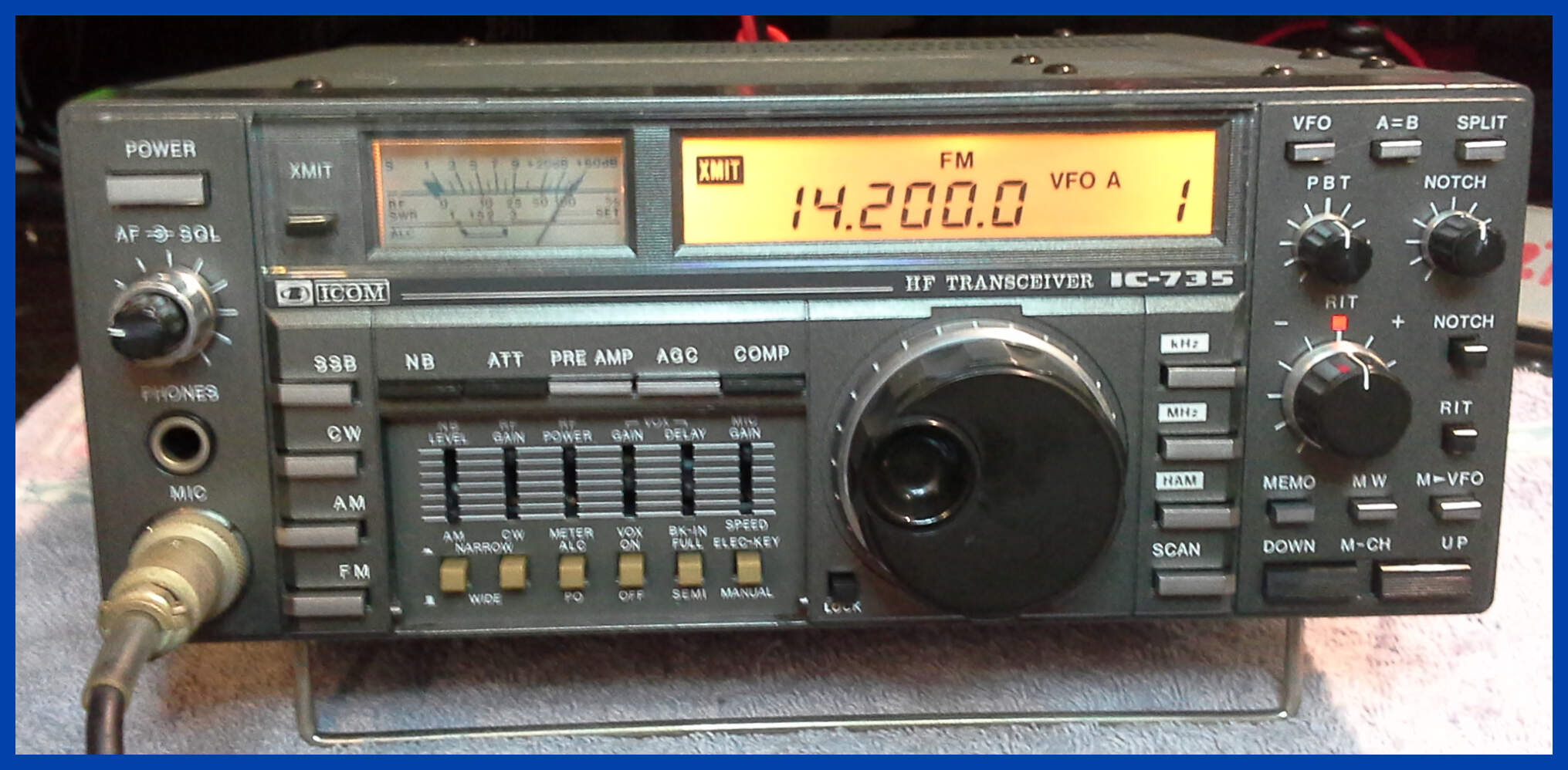
Icom IC-735
This radio arrived with no transmit on any band or any mode, the display lamps had blown so you couldn't see what was going on and the controls were so stiff I don't think they had moved in years, on the plus side receive worked without any problems.
After a lot of work on the PA unit which had both the final and driver bias control faults with the finals having so much bias
that every time you keyed the radio the power lead fuse blew, after the PA was repaired a lot of TLC on the rest of the radio brought it back to a fully functioning condition.
The picture above shows the radio transmitting at full power on FM after the completed repair.
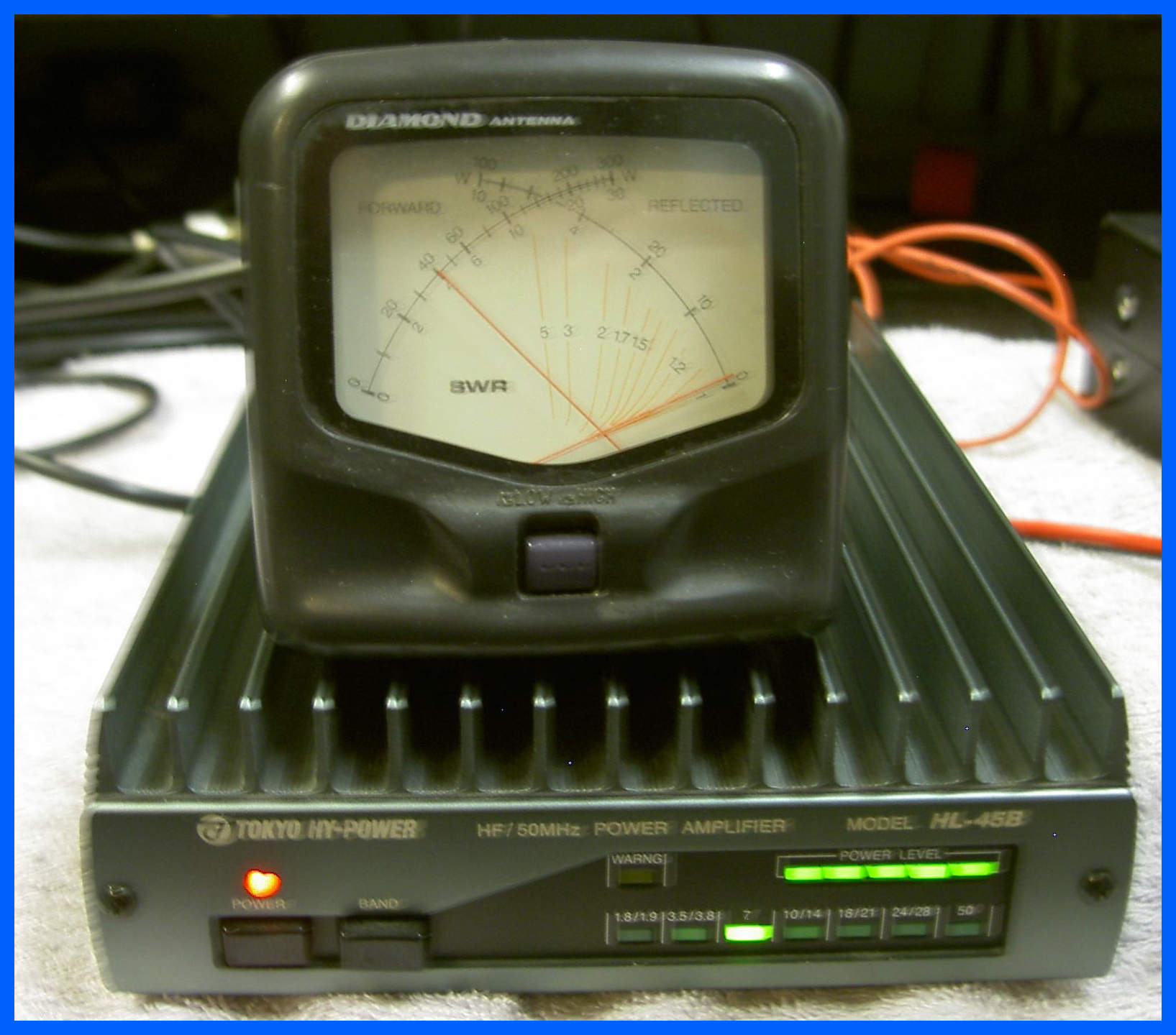
Tokyo Hy-Power HL-45
I have just changed and re-biased the Power Mosfets in this Tokyo Hy-Power RF amplifier, this is the first one I have done as there are not many of these quality products about these days. The picture shows the amplifier transmitting 40 Watts output for 2 Watts of drive.
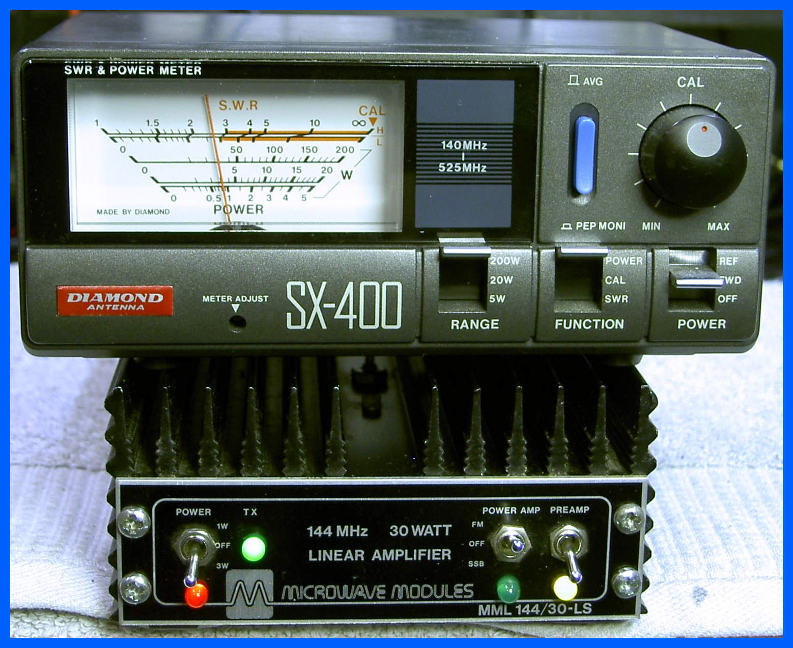
Microwave Modules 144/30 LS
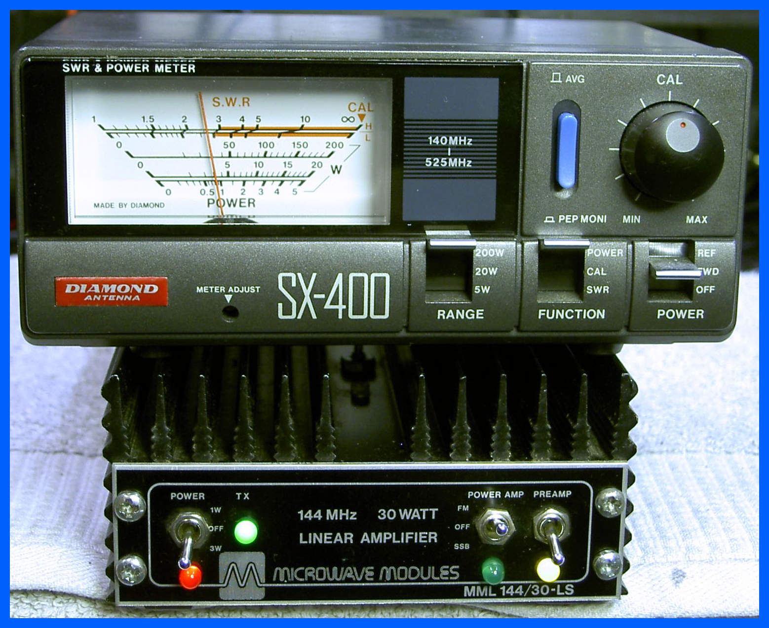
This amp came in with no power output, the transistor tested alright, but the bias current was set to high it was difficult to believe it had ever worked. I turned the bias down to a more reasonable value, further investigation revealed a failed component which was replaced and normal transmit function was restored, and the Rx amp was also tested to confirm that it worked.
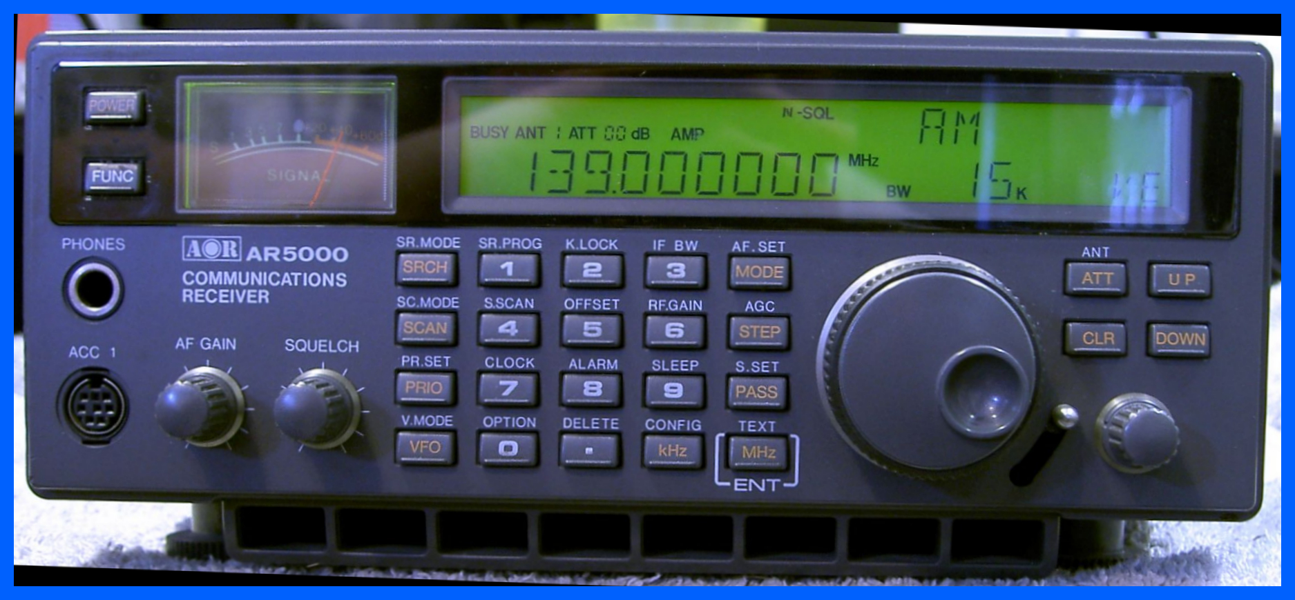
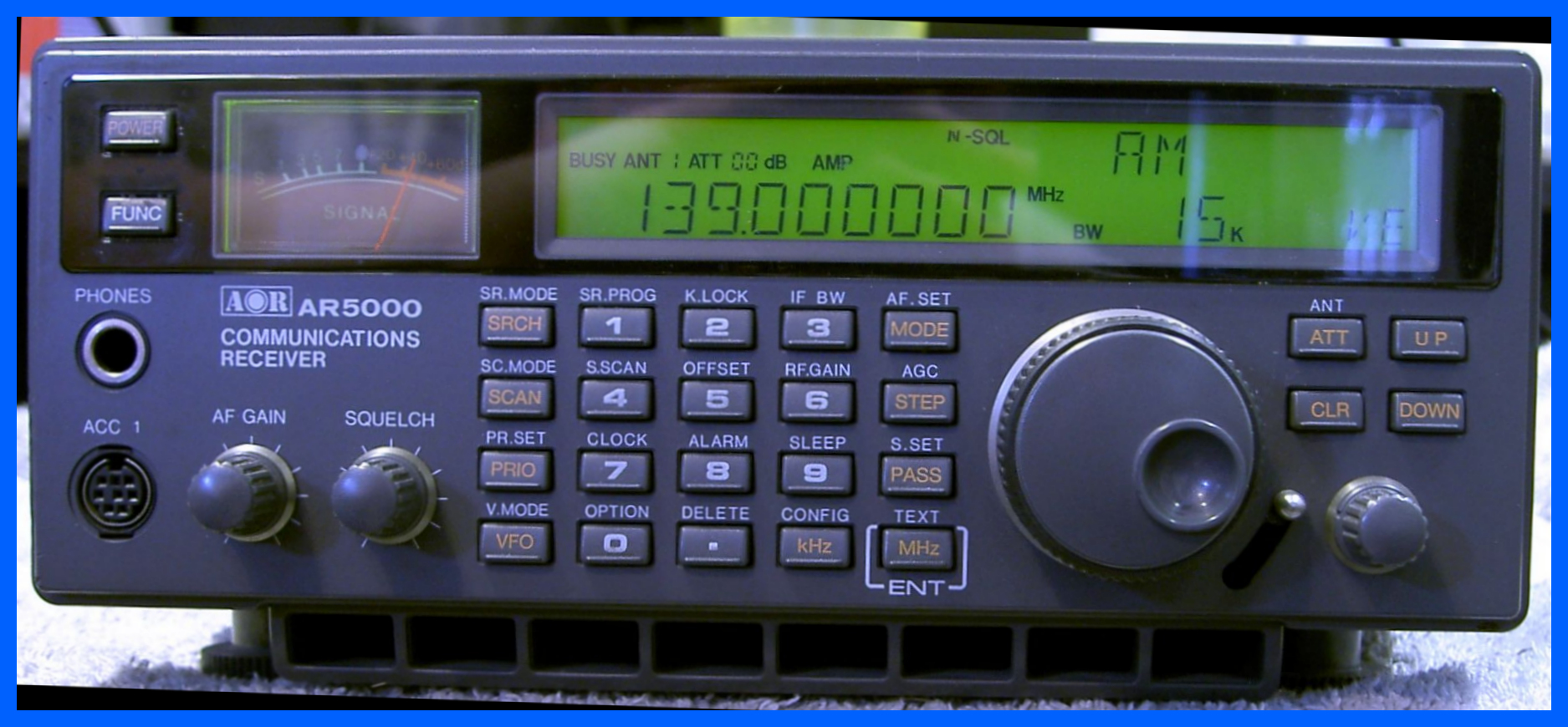
AOR AR5000
This receiver arrived with a unable to receive on AM or
SSB
fault but FM is received alright. You can see from the signal meter in
the picture that after a surface mount component repair the receiver
now receives AM without any problems.
Drake R8E
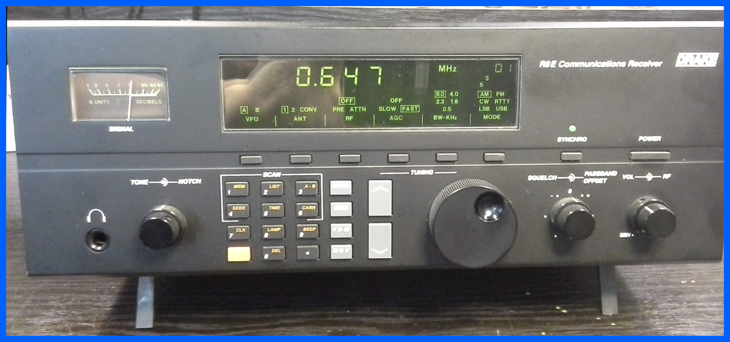
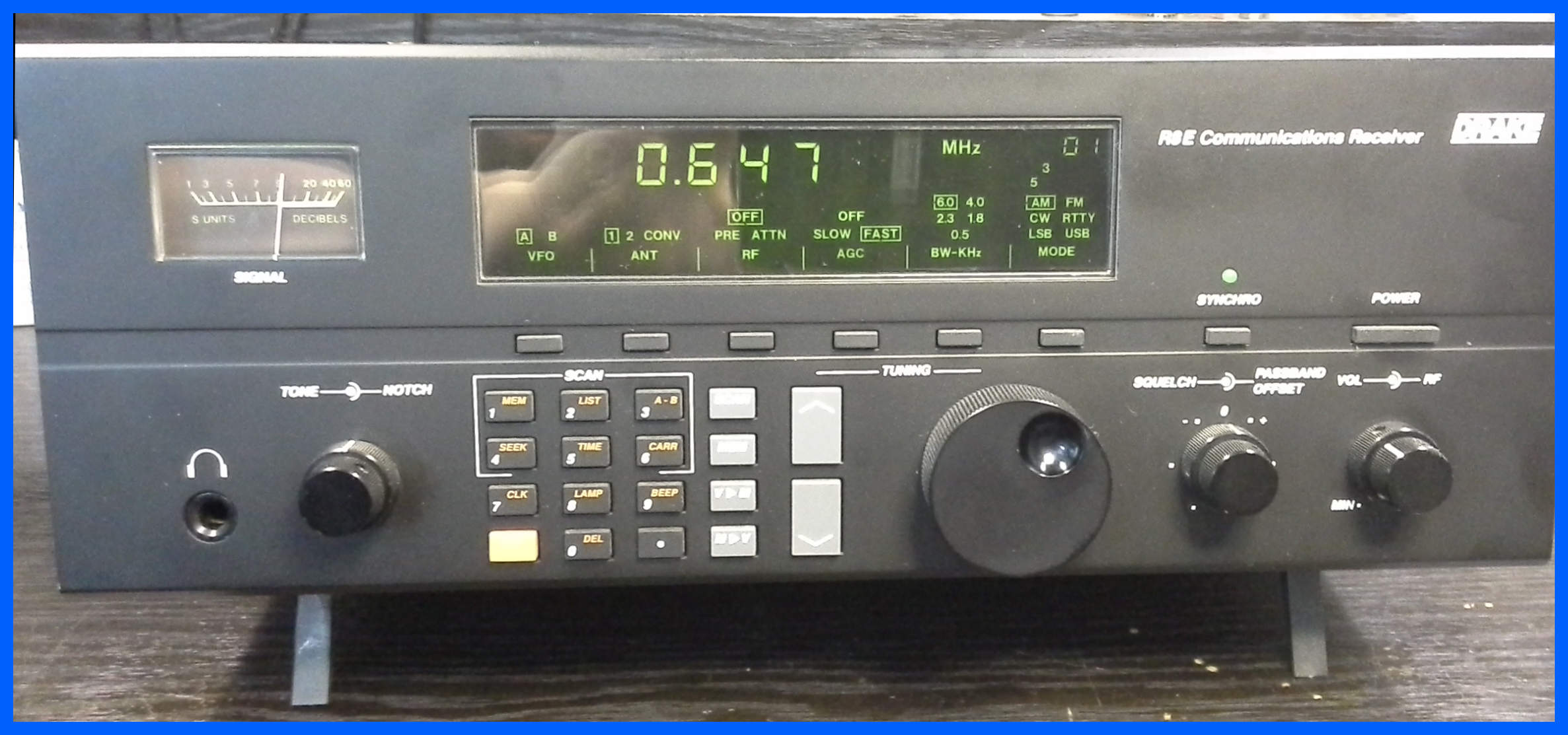
This radio came in with a no receive fault, after performing a quick inspection I found two of its electrolytic capacitors had leaked electrolyte all over the corner of the board and was eating the top tracks off the board. This was quickly cleaned up before the problem got any worse. The receiver had several faults which were identified once the receiver could be operated in safety. It was not possible to perform the normal On-Air test, so I had it on in the workshop tuned to Radio Caroline.
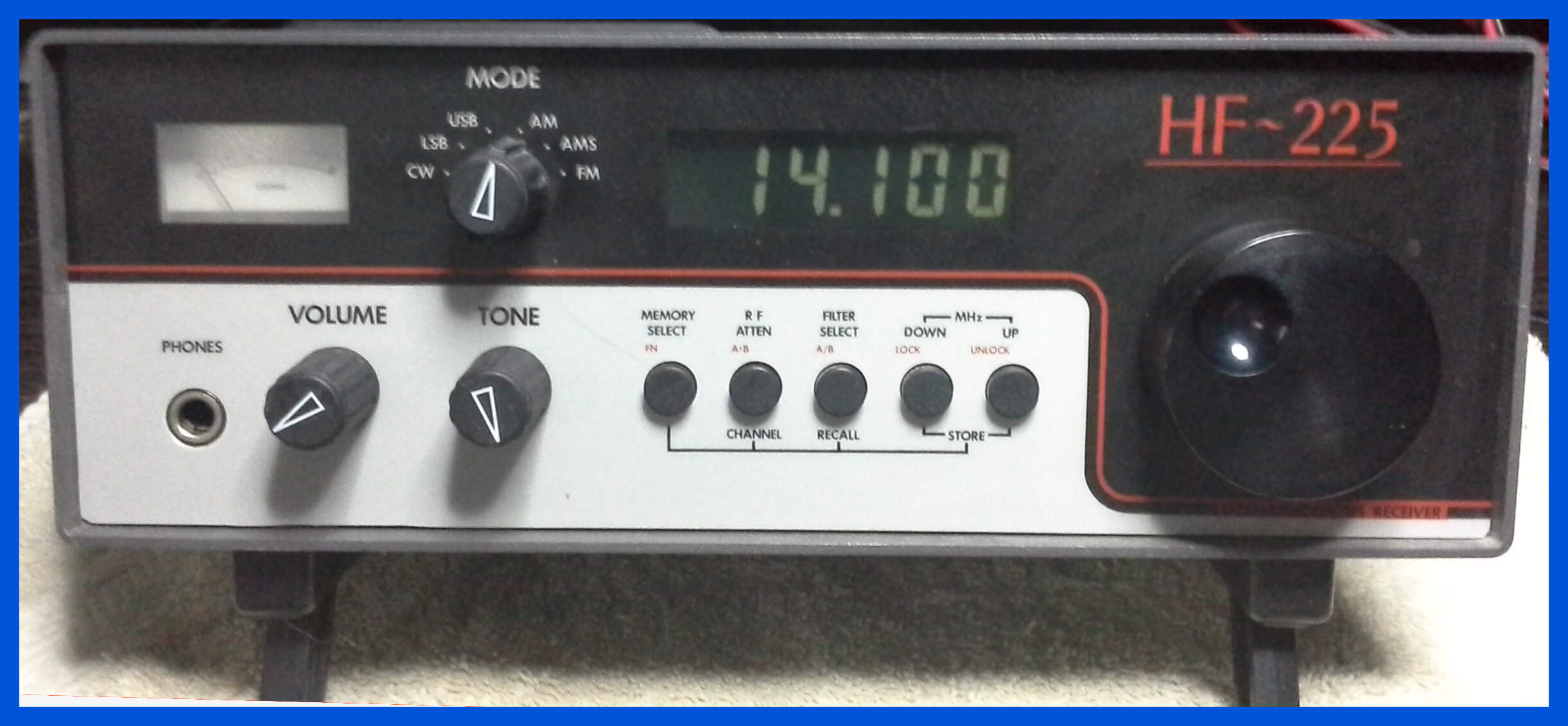
Lowe HF 225 Receiver
This receiver came in with no display when it was turned
on, after a close inspection it also appeared that it required the replacement
of its electrolytic capacitors.
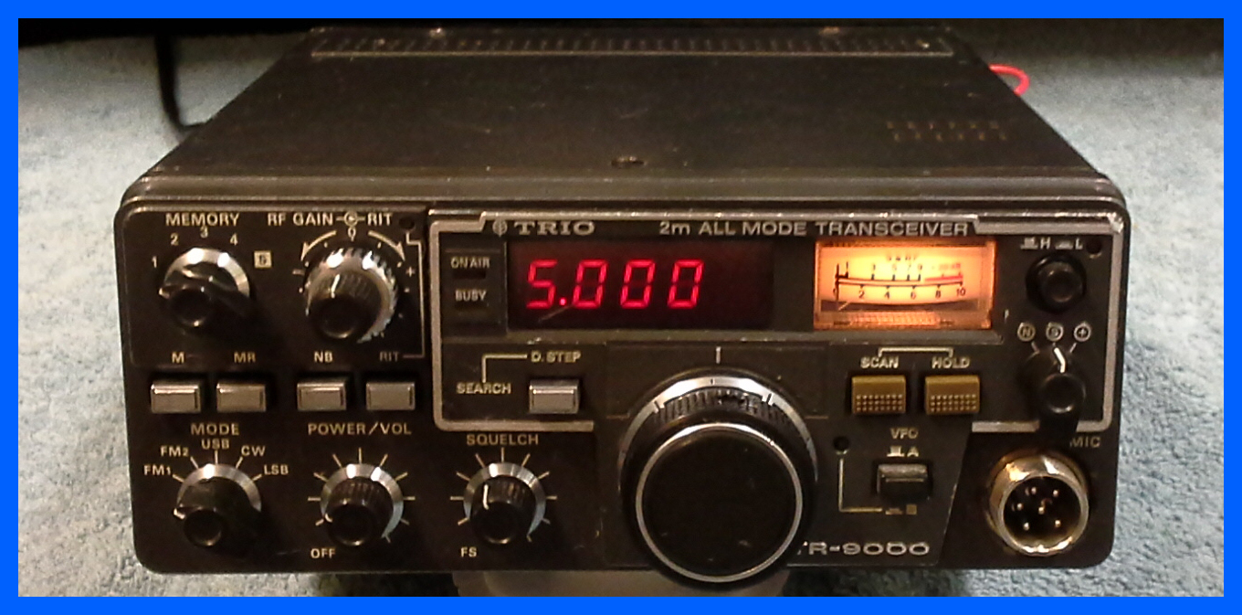
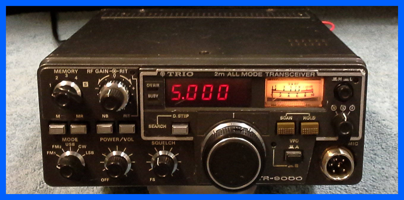
Trio - TR9000
Here is an example of a Trio Multi-mode radio from the early
80’s,
this radios being mono band incorporates a three pole band-pass cavity
filter which filters out the out of band noise which we are all
suffering from these days much more effectively than “The rig in a box”
is able to do.
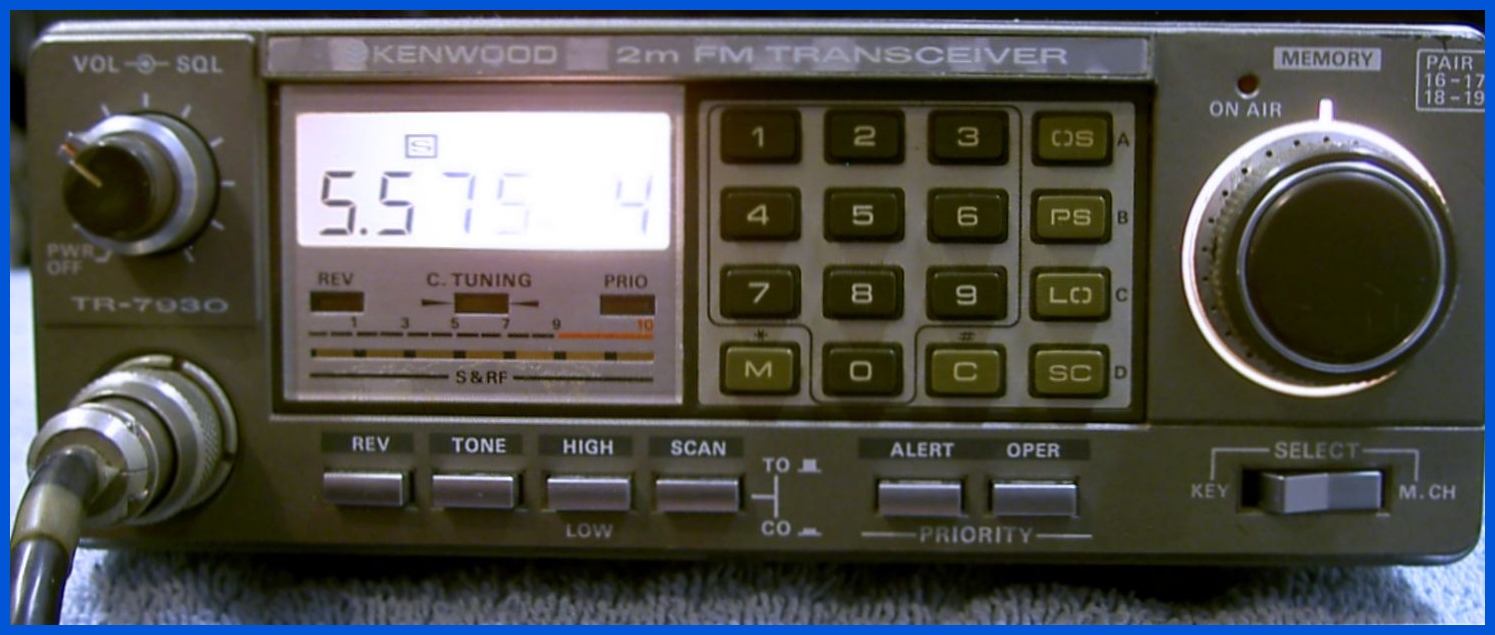
Trio TR-7930
This is a 2-meter mobile transceiver from the early 80s, it came in with a range of
problems including the inability to enter any frequencies into the
radio via the keyboard, all the lamps had blown so you could not see
what was on the display, and there were a number of failed capacitors.
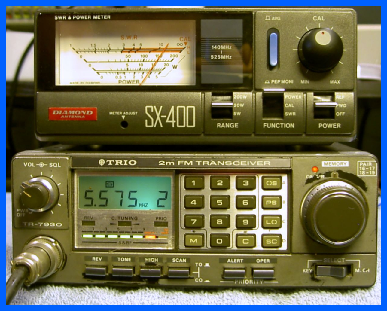
The radio pictured above is the second one that came in the same
consignment, but is somewhat worse for wear, apart from the normal
problems the radios PA block has blown so it only transmits 15Watts as
shown on the power meter, and someone had tried to change the CPU and
had got into difficulty while doing it. This repair took lot of time
but keeping an old piece of equipment going is well worth it.
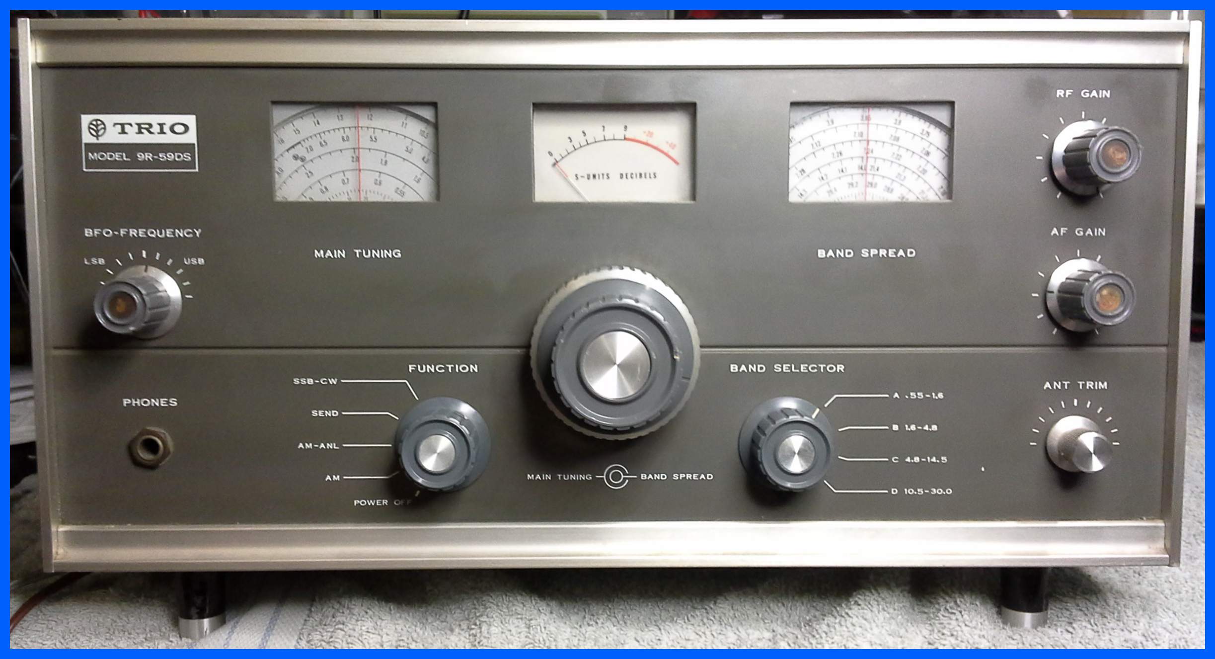
Trio 9R-59DS
This radio came in with reported frequency drift problems, but turned out that it had not been serviced for may years and a significant rebuild was required. This radio was produced between 1968-1969 and at 52 years old is one of the oldest receiver's that I have repaired.
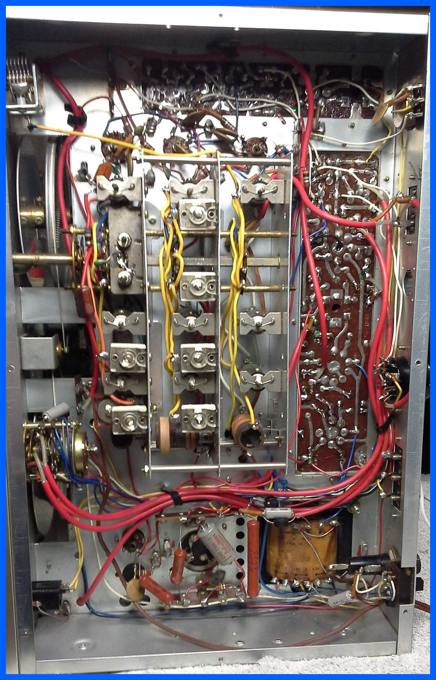
Bottom view of the Trio 9R-59DS.
Those power supply component's next to the mains transformer which are uncovered with bare wires can give you more than a tickle if you touch them by mistake.
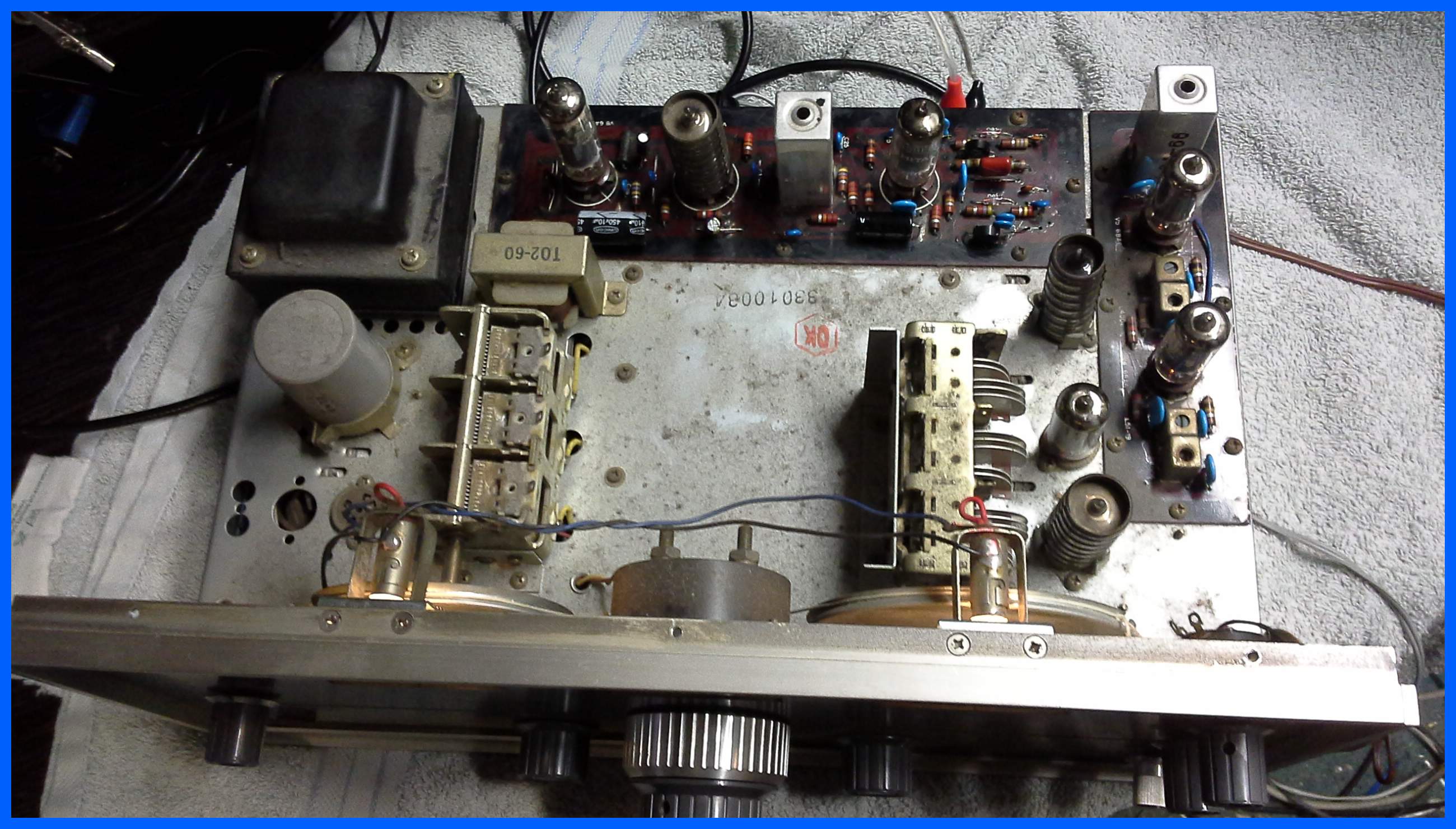
Top view of the Trio 9R-59DS
They just don't make them like they used to with all those thermionic valves.

